Switched reluctance motor for constructing magnetic circuit based on modularizing way

A switched reluctance and modular technology, applied in electrical components, electromechanical devices, etc., can solve the problems of small size of switched reluctance motors, inability to meet the requirements of traction motors, restricting the development trend of switched reluctance motors, etc. damage, and the effect of expanding the scope of application

Inactive Publication Date: 2010-12-01
DONGMING MOTOR ELECTRICSHENZHEN CO LTD
View PDF1 Cites 5 Cited by
  • Summary
  • Abstract
  • Description
  • Claims
  • Application Information

AI Technical Summary

Problems solved by technology

However, due to technical limitations in manufacturing amorphous alloy strips, the maximum width of amorphous alloy strips can only reach 84mm at present. If the above-mentioned stator core preparation method is used to manufacture switched reluctance motors, the stator and/or Or the magnetic circuit part of the rotor can only be made ve

Method used


Image

  • Switched reluctance motor for constructing magnetic circuit based on modularizing way
  • Switched reluctance motor for constructing magnetic circuit based on modularizing way
  • Switched reluctance motor for constructing magnetic circuit based on modularizing way

Examples


Example Embodiment

[0034] The preferred embodiments shown in the accompanying drawings will be described in further detail below.

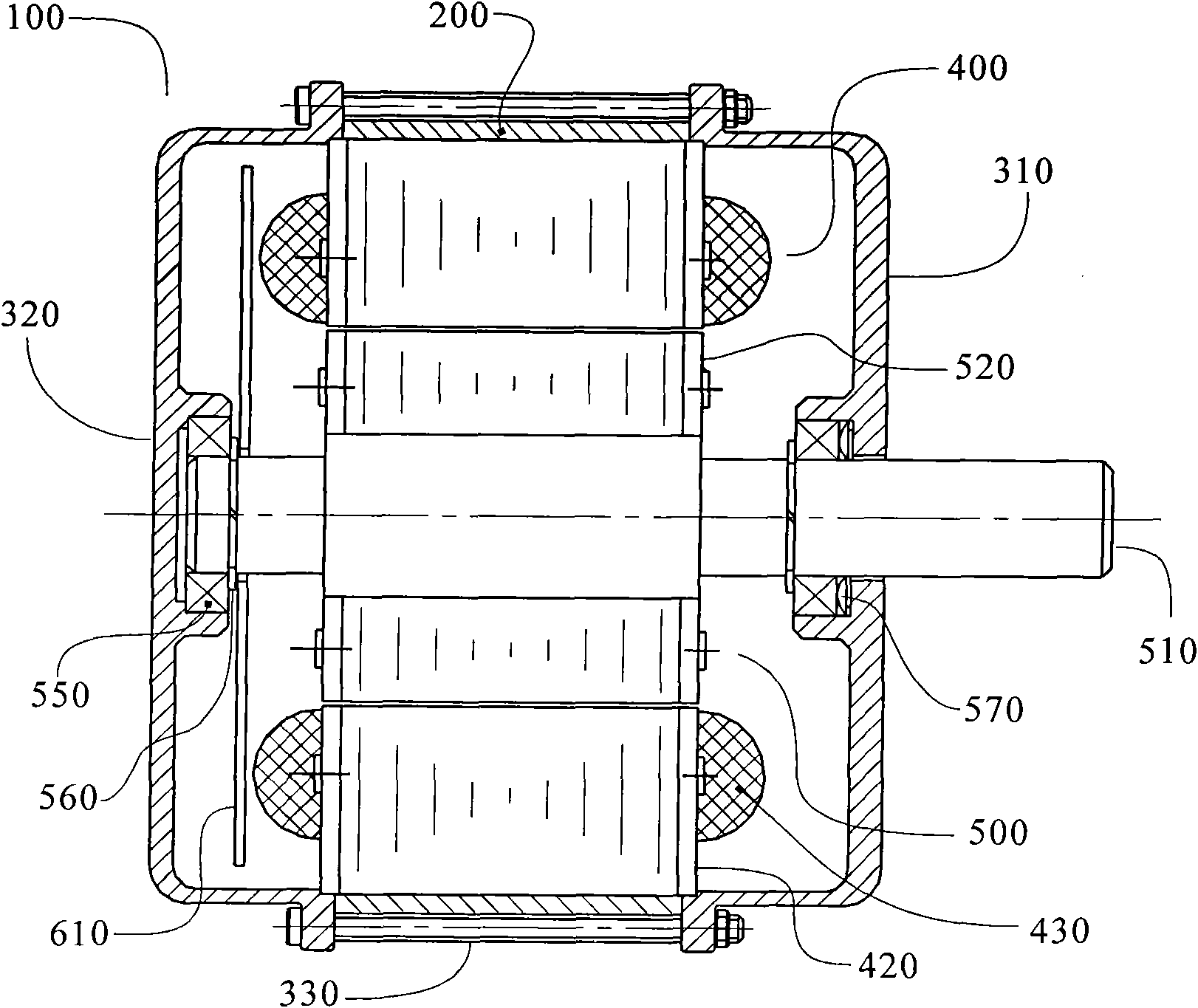
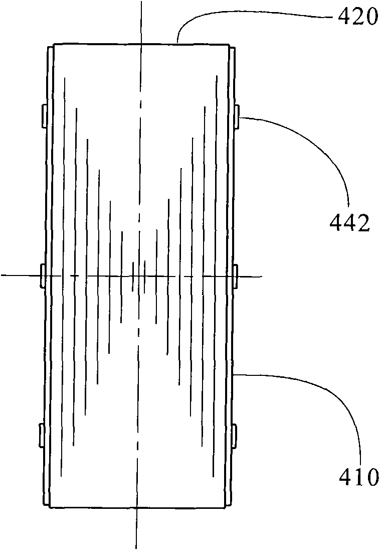
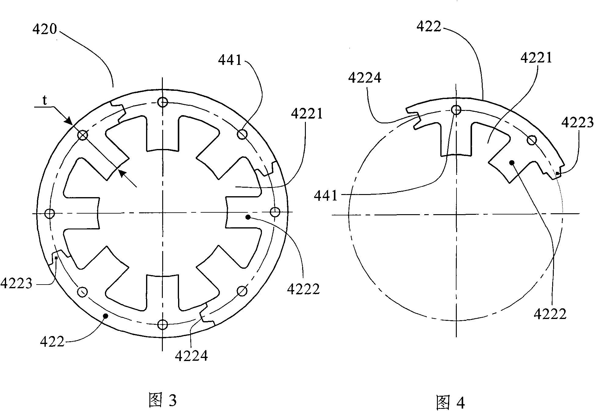
[0035] The present invention is based on a switched reluctance motor that constructs at least a stator magnetic circuit in a modular manner, such as figure 1 As shown, it includes a housing 200, a front end cover 310, a rear end cover 320, a stator 400 with concentrated windings wound around each magnetic pole, and a rotor 500 with a salient pole structure. The magnetic circuit part 520 of the rotor 500 is tightly fitted or fixed on the motor shaft 510 by means of a coupling key, and each salient pole on the rotor magnetic circuit part 520 is not wound with any form of winding. The axial end of the stator 400 is provided with a rotor position sensor 600 . In particular, if Figure 2 to Figure 4 As shown, the iron core portion 420 of the stator 400 includes N pieces of stator modules 422 connected to each other and forming a circular cross-section cylinder. The st...


PUM


Abstract

The invention relates to a switched reluctance motor for constructing a magnetic circuit based on a modularizing way, which comprises a shell (200), a front end cover (310), a back end cover (320), a stator (400) and a rotor (500), wherein a concentrated winding is wound on each magnetic pole of the stator (400); the rotor (500) has a salient pole structure; a magnetic circuit part (520) of the rotor (500) is tightly matched or fixed on a crankshaft (510) by a connecting key; and salient poles on the magnetic circuit part (520) are not wound on the winding in any form. Particularly, an iron core part (420) of the stator (400) and/or the magnetic circuit part (520) of the rotor (500) are respectively constructed by N respective noncrystal alloy stator modules (422) and M noncrystal alloy rotor modules (522). The stator magnetic circuit and the rotor magnetic circuit of the switched reluctance motor of the invention are made of noncrystal alloy, thereby reducing the iron loss of the switched reluctance motor, being free from the limitation of the maximal width of a noncrystal alloy belt material and expanding the application range of the switched reluctance motor.

Description

technical field [0001] The present invention relates to switched reluctance motors, in particular to switched reluctance motors which use amorphous alloy laminations to construct stator and / or rotor magnetic circuits. Background technique [0002] The prior art reluctance synchronous motor is a synchronous motor which utilizes the unequal reluctance of the direct axis and the quadrature axis of the rotor to generate reluctance torque. Switched Reluctance Motor, referred to as SRM, is a synchronous motor developed since the mid-1980s on the basis of the reluctance synchronous motor, including a stator and a rotor with a salient pole structure. For the structure of sheet 420' and rotor punching sheet 520' see Figure 10 . The structure of the SRM is simple and strong, without any form of winding on the rotor, and problems such as poor cage casting and use of interrupted bars in the manufacturing process of the squirrel cage induction motor will not occur; at the same time, it...

Claims


Application Information

Patent Timeline
IPC IPC(8): H02K29/00H02K29/06
Inventor 石雷卢娟谢伟
Owner DONGMING MOTOR ELECTRICSHENZHEN CO LTD
Why Eureka
Try Eureka