Electromagnetic coupling excitation speed governor

A technology of electromagnetic coupling and governor, applied in the direction of asynchronous induction clutch/brake, electrical components, electromechanical devices, etc., can solve the problems of high failure rate assembly conditions, harmonic pollution of power grid, complex structure, etc., and achieve structural and Simple assembly, reduced excitation loss, and improved transmission efficiency

Active Publication Date: 2010-12-01
上海鑫扬电器有限公司
View PDF0 Cites 1 Cited by
  • Summary
  • Abstract
  • Description
  • Claims
  • Application Information

AI Technical Summary

Problems solved by technology

[0005]Therefore, there is an urgent need for a new motor speed controller to overcome the existing technology of high energy consumptio

Method used


Image

  • Electromagnetic coupling excitation speed governor
  • Electromagnetic coupling excitation speed governor
  • Electromagnetic coupling excitation speed governor

Examples


Embodiment 1

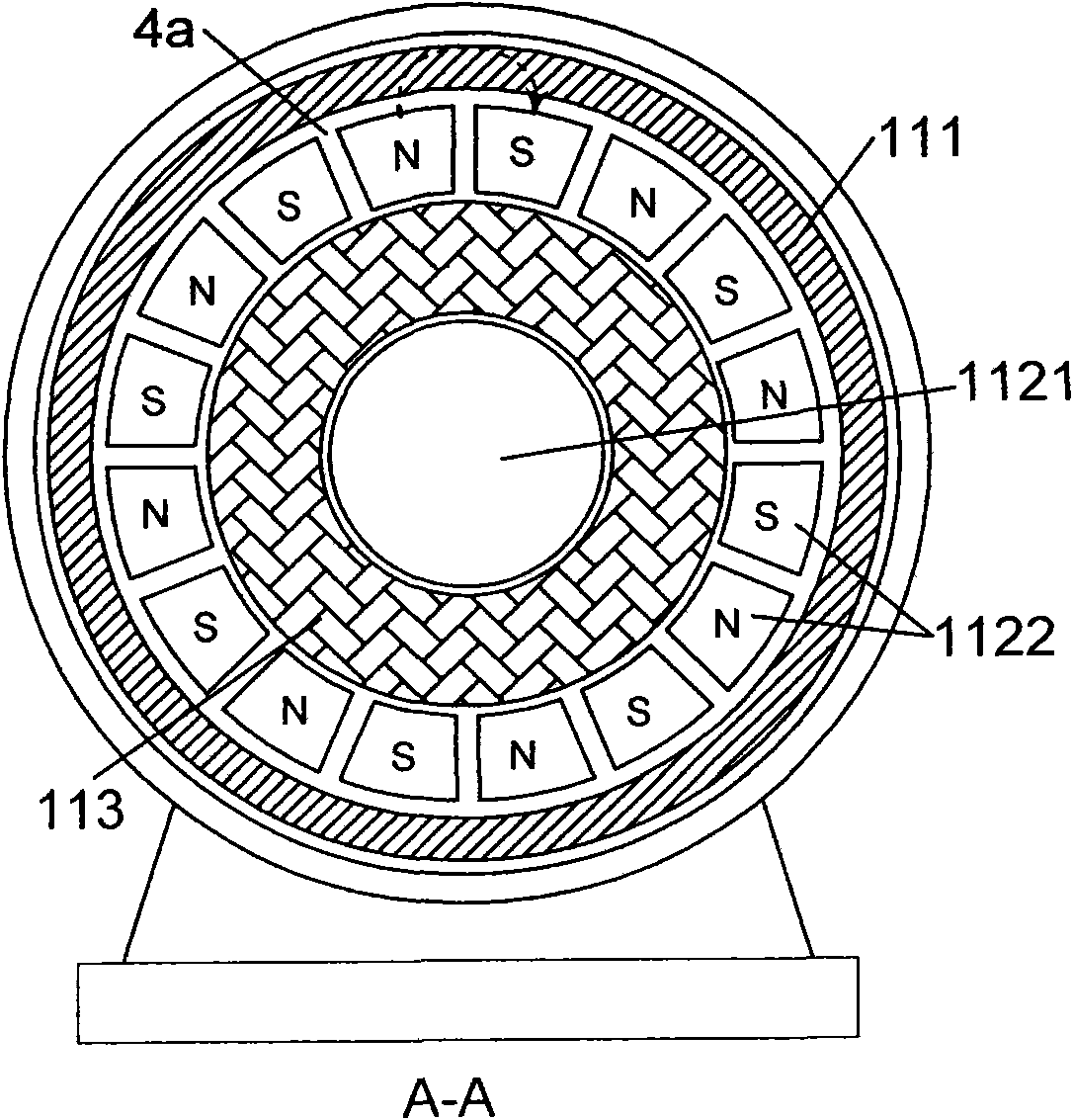
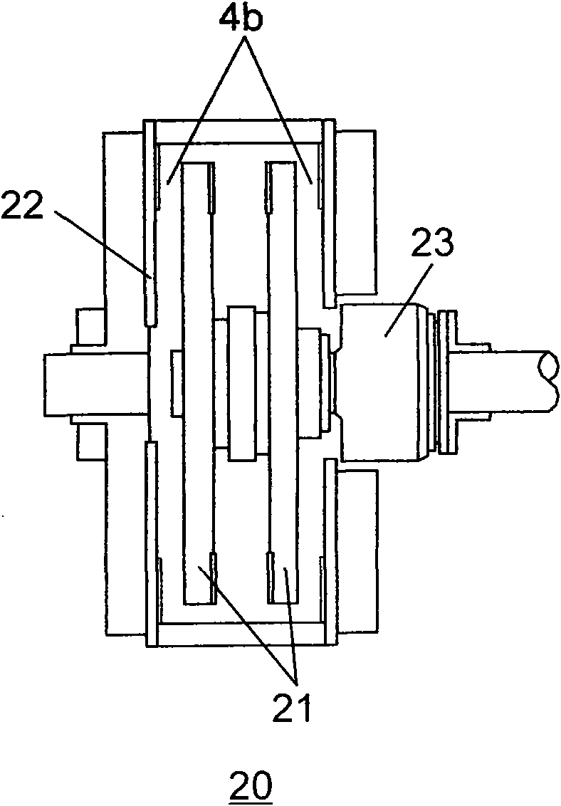
[0031] see Figure 4 ~ Figure 7 As shown, the electromagnetic coupling excitation governor 30 of the present invention is basically the same as the electromagnetic slip clutch 10 of the prior art, and is also connected between the motor 1 and the load, including a casing 31 and an external rotating shaft arranged in the casing 31. The body 32 , the inner rotating body 33 arranged in the outer rotating body 32 , and the field winding 34 wound on the inner rotating body 33 . Please combine Figure 5 ~ Figure 7 As shown, the difference is that the outer rotating body 32 is a magnetic conductor with a cylindrical structure as a whole, one end of the outer rotating body 32 is connected to the output shaft of the motor 1, and the inner surface of the outer rotating body 32 is provided with a magnet for generating an induced current. of conductors. The outer rotating body 32 is formed by stacking silicon steel sheets, and the inner surface of the outer rotating body 32 is uniformly...

Embodiment 2

[0060] see Figure 10 ~ Figure 12 As shown, the electromagnetic coupling excitation governor 40 of the present invention is basically the same as the governor 30 of Embodiment 1, and is also connected between the motor and the load, including a casing 41 and an external rotating body 42 inside the casing 41 , the inner rotating body 43 arranged in the outer rotating body 42 and the field winding 44 wound on the inner rotating body 43 . In addition, the external rotating body 42 is a cylindrical magnetic conductor as a whole, one end of the external rotating body 42 is connected to the output shaft of the motor, and the inner surface of the external rotating body 42 is provided with a conductor for generating an induced current. The difference is that the outer rotating body 42 of the governor 40 is a pure iron cylinder, or it can also be a cylinder of other magnetically permeable materials; The ring 421 is tightly fixed on the inner surface of the external rotating body 42 by...


PUM

PropertyMeasurementUnit
Thicknessaaaaaaaaaa

Abstract

The invention discloses an electromagnetic coupling excitation speed governor which is connected between an electric motor and a load and comprises an outer shell, an outer rotator, an inner rotator and an excitation winding. The outer rotator is a magnetizer in a whole cylindrical structure, one end of the outer rotator is connected with an output shaft of the electric motor, and a conductor for generating an induction current is arranged on the inner surface of the outer rotator. When the excitation winding is energized, a plurality of pairs of magnetic poles between an N phase and an S phase are generated on the outer surface of the inner rotator which rotates together with the conductor of the outer rotator through electromagnetic coupling, and the aim of controlling speed is achieved by changing an excitation current. The speed governor can lessen the excitation loss, improve the transmission efficiency, has simple structure and assembly without harmonic pollution to a power grid, not only prolongs the service life, but also decreases the cost.

Description

technical field [0001] The invention relates to the speed regulation technology of electric motors, and more specifically relates to an electromagnetic coupling excitation speed governor, which can reduce energy consumption and improve transmission efficiency. Background technique [0002] Since the advent of AC asynchronous motors, many scientific and technological workers have made unremitting efforts to realize simple, economical, reliable and efficient speed regulation technology. Slip clutches appeared as early as the 1960s, and later developed into electromagnetic speed-regulating motors. From that time, it mainly solved the problem of a wide range of speed regulation, but failed to take into account the problems of energy consumption and efficiency. refer to figure 1 , figure 2 As shown, the electromagnetic variable speed motor 10 includes an electromagnetic slip clutch 11 and a squirrel-cage asynchronous motor 1. The electromagnetic slip clutch 11 includes an out...

Claims


Application Information

Patent Timeline
IPC IPC(8): H02K49/02H02K51/00
Inventor 陈品森陈铭明
Owner 上海鑫扬电器有限公司
Why Eureka
Try Eureka