Supercharge Your Innovation With Domain-Expert AI Agents!

Method of calibrating a constant voltage supply for an ultrasonic transducer of a wire bonding machine

An ultrasonic transducer, wire bonding machine technology, applied in the direction of semiconductor devices, electric solid devices, fluids utilizing vibration, etc.

Active Publication Date: 2010-12-01
KULICKE & SOFFA IND INC
View PDF0 Cites 6 Cited by
  • Summary
  • Abstract
  • Description
  • Claims
  • Application Information

AI Technical Summary

Problems solved by technology

Thus, a system with a lower impedance will undesirably result in more energy being applied to the bond than a system with a higher impedance when using constant voltage control mode
[0008] In this way, there are obvious limitations in both the traditional constant current and constant voltage control modes

Method used


Image

  • Method of calibrating a constant voltage supply for an ultrasonic transducer of a wire bonding machine
  • Method of calibrating a constant voltage supply for an ultrasonic transducer of a wire bonding machine
  • Method of calibrating a constant voltage supply for an ultrasonic transducer of a wire bonding machine

Examples


Embodiment Construction

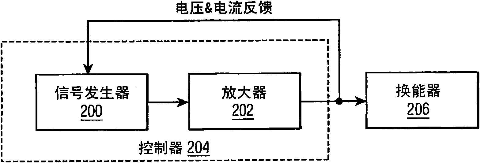
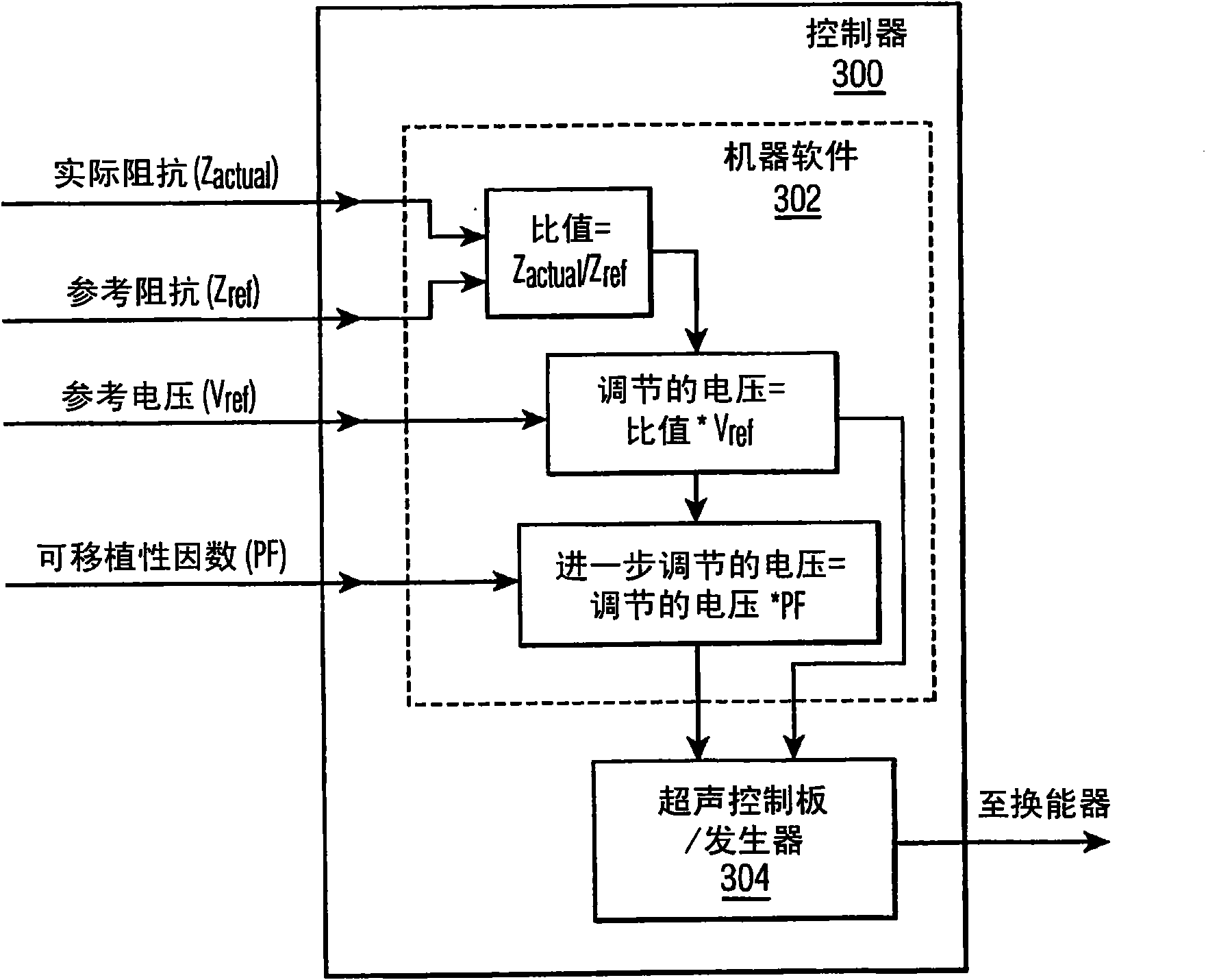
[0019] According to some exemplary embodiments of the present invention, a constant voltage control mode is used to power an ultrasonic transducer of a wire bonding system. In some applications, constant voltage is preferred, for example, because the constant voltage mode tends to be less sensitive to poor wire pin clamping and other potential problems such as wire pin resonance conditions. To overcome the portability issues of conventional constant voltage control schemes, the impedance of the ultrasound transducer (and / or the impedance associated with the operation of the ultrasound transducer) can be used to normalize the magnitude output of the voltage.

[0020] By using the improved constant voltage mode described here, several advantages can be achieved, including, for example, improved second bonding on applications with wire pins susceptible to resonance, while still maintaining machine-to-machine portability performance and compensates for changes in system impedance ...


PUM


Abstract

A method of calibrating a voltage for use with an ultrasonic transducer of a wire bonding machine in a constant voltage mode is provided. The method includes: (1) determining an impedance value associated with operation of the ultrasonic transducer; and (2) establishing an adjusted voltage level for use with the ultrasonic transducer in the constant voltage mode based on the determined impedance value.

Description

technical field [0001] The present invention relates to the application of energy to ultrasonic transducers of wire bonding machines, and more particularly to an improved method of applying a constant voltage to ultrasonic transducers. Background technique [0002] When handling and packaging semiconductor devices, wire bonding continues to be the primary method of providing electrical interconnection between two locations within a package, such as between a die pad of a semiconductor die and wires of a lead frame. More specifically, a wire bonder (also known as a wire bonder) is used to form loops of wire between the various locations that will be electrically interconnected. [0003] An exemplary conventional wire bonding sequence includes: (1) forming a free air ball on the end of a wire extending from a bonding tool; (2) using the free air ball on the die of a semiconductor die. forming a first bond on the pad; (3) extending the length of the lead in a desired shape bet...

Claims


Application Information

Patent Timeline
Patent Type & Authority Applications(China)
IPC IPC(8): B06B1/02
CPCB06B1/0223H01L24/78H01L2224/78301H01L2924/00014H01L2224/45015H01L2924/207H01L2224/45099
Inventor 秦巍T·J·科洛西莫J·D·莫尔纳
Owner KULICKE & SOFFA IND INC
Features
  • R&D
  • Intellectual Property
  • Life Sciences
  • Materials
  • Tech Scout
  • Unparalleled Data Quality
  • Higher Quality Content
  • 60% Fewer Hallucinations
Learn More