Device for cooling hot gas to be discharged from an aircraft

A technology for cooling air and aircraft, applied in the field of hot air devices, can solve problems such as increasing direct operating costs, increasing aircraft resistance, etc., and achieve the effects of saving thermal insulation materials and weight, reducing the number, and increasing the strength of components

Inactive Publication Date: 2010-12-01
AIRBUS OPERATIONS GMBH
View PDF12 Cites 8 Cited by
  • Summary
  • Abstract
  • Description
  • Claims
  • Application Information

AI Technical Summary

Problems solved by technology

However, air deflectors on the outer profile have the disadvantage of increasing the drag of the aircraft and thus the direct operating costs

Method used


Image

  • Device for cooling hot gas to be discharged from an aircraft
  • Device for cooling hot gas to be discharged from an aircraft
  • Device for cooling hot gas to be discharged from an aircraft

Examples


Embodiment Construction

[0021] For a better understanding, several embodiments of the device according to the present invention will be described below in conjunction with an embodiment integrated, for example, in an Airbus A400M military transport aircraft. The device according to the invention is not limited to cooling APU exhaust gases, but can also cool other hot gases from other systems, for example from fuel cells. The general term "hot gas" is used in some contexts below. The turbine exhaust from the APU is considered a specific form of hot gas.

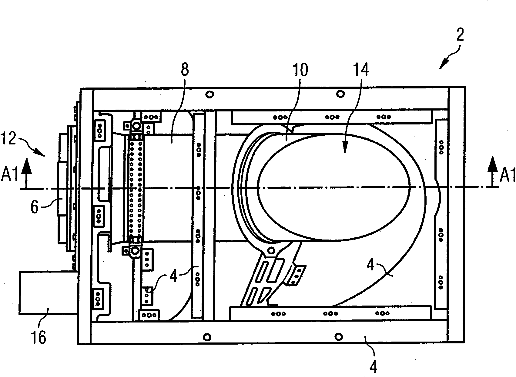
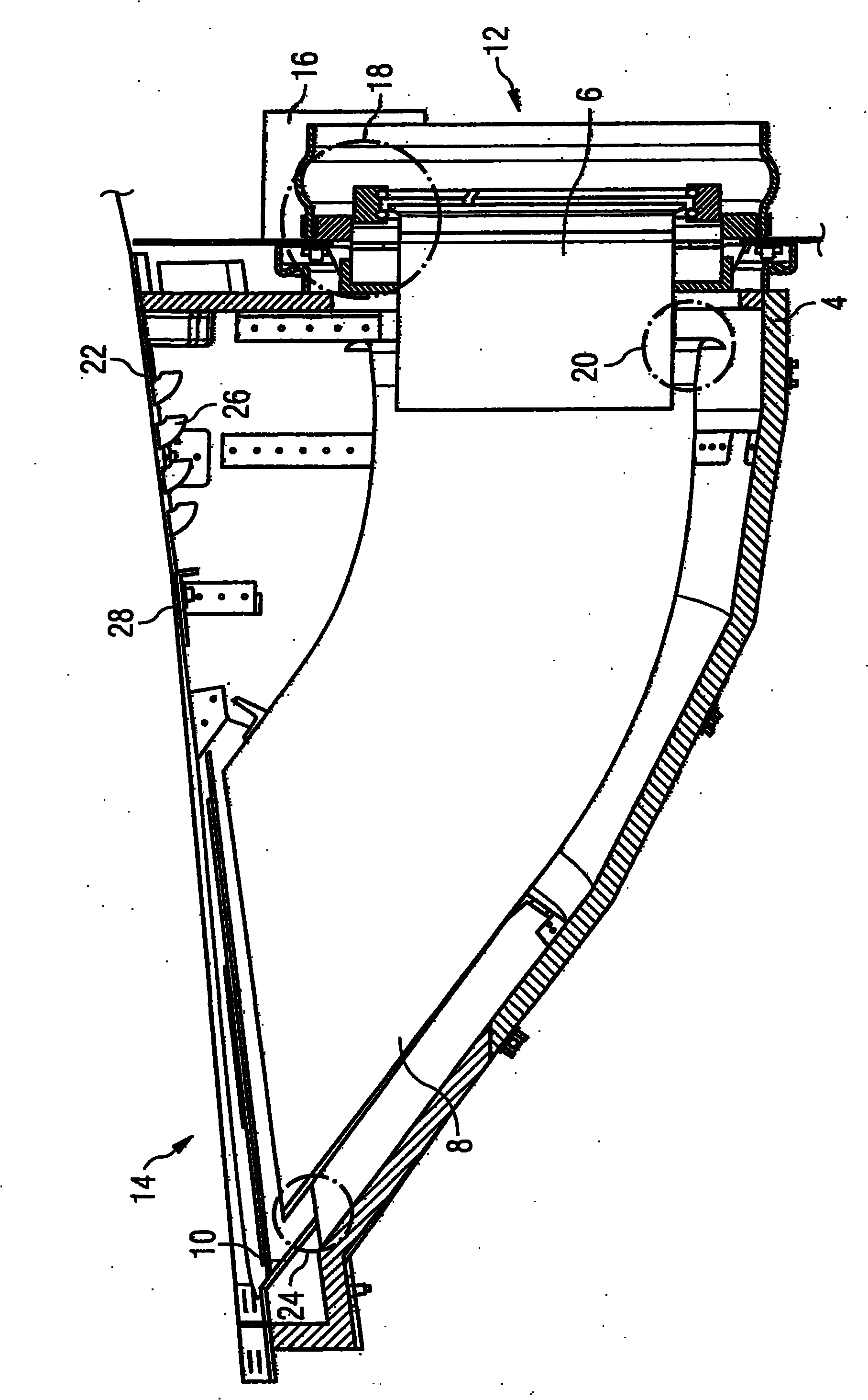
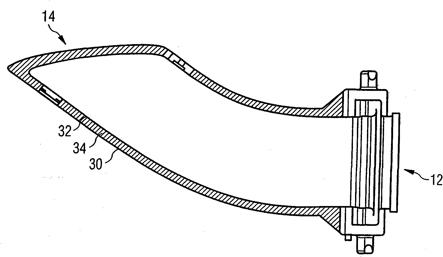
[0022] figure 1 An exhaust system 2 is shown in which, for better illustration, the housing cover installed during operation has been removed. The exhaust system 2 comprises a housing 4 formed of sheet metal troughs, reinforcement members, holders and accessories, and an exhaust system consisting of three continuous exhaust pipes 6, 8 and 10 extending into the housing 4 from an exhaust gas inlet location 12. Exhaust pipe. The exhaust pipe 6 guide...


PUM


Abstract

The invention relates to a device (2) for cooling hot gas that is to be discharged from an aircraft. Said device (2) comprises a duct (6, 8, 10) for conducting the hot gas from a hot gas source that can be connected to the device to a discharge point, and a frame (4) which surrounds the duct and is used for mounting the duct. The duct is formed from one or more pipe sections (6, 8, 10) and has one or more cooling air intake points (20, 24) which can be connected to one or more cooling air sources (16) in order to mix the hot gas with cooling air.

Description

technical field [0001] The invention relates to a device for cooling hot gases to be discharged from an aircraft. Background technique [0002] The hot gases to be emitted from the aircraft originate, for example, from the operation of an auxiliary power unit (hereinafter also referred to as “APU”) which produces hot gases in the form of exhaust gases at temperatures up to 730°. The hot gases generated in the APU should be discharged to the environment in as cool a form as possible, so that the stresses in the structure and / or skin of the aircraft caused by local temperature peaks are kept as small as possible. In addition, especially in military aircraft, it is required that the thermal signature of the aircraft is as weak as possible, so that the aircraft cannot be located or identified by means of the thermal signature. [0003] In civil aircraft, the APU is mainly arranged in the tail cone. Due to the aerodynamic flow conditions, however, no special measures are requir...

Claims


Application Information

Patent Timeline
Patent Type & Authority Applications(China)
IPC IPC(8): B64D33/04B01F5/04F04F5/46
CPCY02T50/44B64D41/00B64D2041/002B01F5/049B01F5/0471B01F5/0413B64D2033/045Y02T50/40B01F25/31432B01F25/314B01F25/312
Inventor 马库斯·皮斯克
Owner AIRBUS OPERATIONS GMBH
Why Eureka
Try Eureka