Replacement structure of ratchet wrench

A ratchet wrench and wheel groove technology, applied in the direction of wrenches, screwdrivers, manufacturing tools, etc., can solve the problems of inconvenient replacement and use, insufficient torque resistance, shortened service life, etc., to achieve smooth and convenient replacement, avoid loss of components, and prolong The effect of service life

Inactive Publication Date: 2013-06-05
巨琩有限公司
View PDF0 Cites 1 Cited by
  • Summary
  • Abstract
  • Description
  • Claims
  • Application Information

AI Technical Summary

Problems solved by technology

[0004] But in its actual use, there are some problems, such as figure 1 , figure 2 As shown, the stopper 25 is embedded in the limit ring groove 22 of the sleeve wheel 20 by using the stopper 27 in the middle section. Under the influence of machining accuracy, the bottom edge of the stopper 25 cannot be effectively attached Butt against the surface of the abutting edge 120 of the wheel groove 12, so the stopper 25 is suspended, and the stopper 25 is pushed through the push rod 28 passing through the cover 16, because the user pushes the push rod with fingers 28. Its force application point is easy to form a force application arm with the push column 29 against the stopper 25, which will cause the stopper 25 to tilt to the force application side of the push rod 28 [such as figure 2 Shown], and then make the limit protrusion 27 of the detent 25 and the limit ring groove 22 of the set wheel 20 have the problem of jamming and wear, which affects the convenience of replacing the set wheel 20, and even shortens its use. life;
[0005] Furthermore, the limit ring groove 22 of the set wheel 20 and the limit projection 27 of the stopper 25 are located in the middle section, so when the two are combined, affected by the difficulty of processing, the set wheel 20 and the stopper 25 The number and area of ​​the ratchets 2126 will be reduced, so that it is easy to cause gaps and inaccurate engagement between the catch 25 and the ratchet 2621 tooth surfaces of the set wheel 20, resulting in the gap between the set wheel 20 and the catch 25. The ratchet 2126 has the phenomenon of jumping or collapsing due to inaccurate locking, so it has the problem of insufficient torque resistance
[0006] In addition, the stopper 25 utilizes the cover plate 16 to restrict it from falling off when the set wheel 20 is replaced. In order to limit the stopper 25, its push groove 17 cannot form an open shape, so the diameter of the pushrod 28 of the stopper 25 is limited. , affecting its structural strength and service life
If in order to increase the diameter of the push rod 28, the moving groove 17 of the cover sheet 16 is changed into an open shape, then after taking out the sleeve wheel 20, the stopper 25 may fall because it is no longer restricted, so it will cause Together with the push post 29 and the elastic part 290 behind the catch 25, the push post 29 and the elastic part 290 are small in size, and there is a problem of missing components, which causes inconvenience in replacement and use.

Method used


Image

  • Replacement structure of ratchet wrench
  • Replacement structure of ratchet wrench
  • Replacement structure of ratchet wrench

Examples


Embodiment Construction

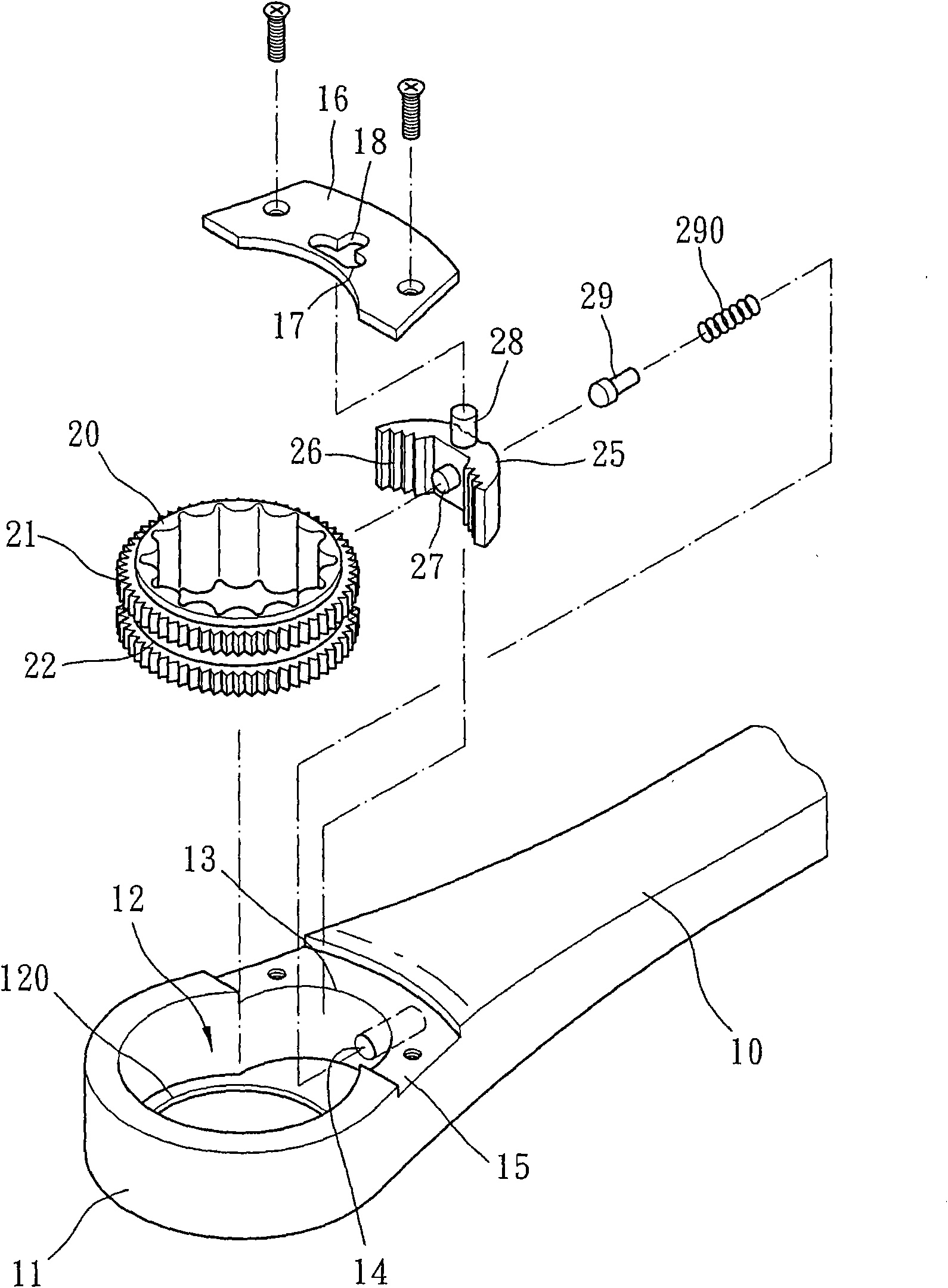
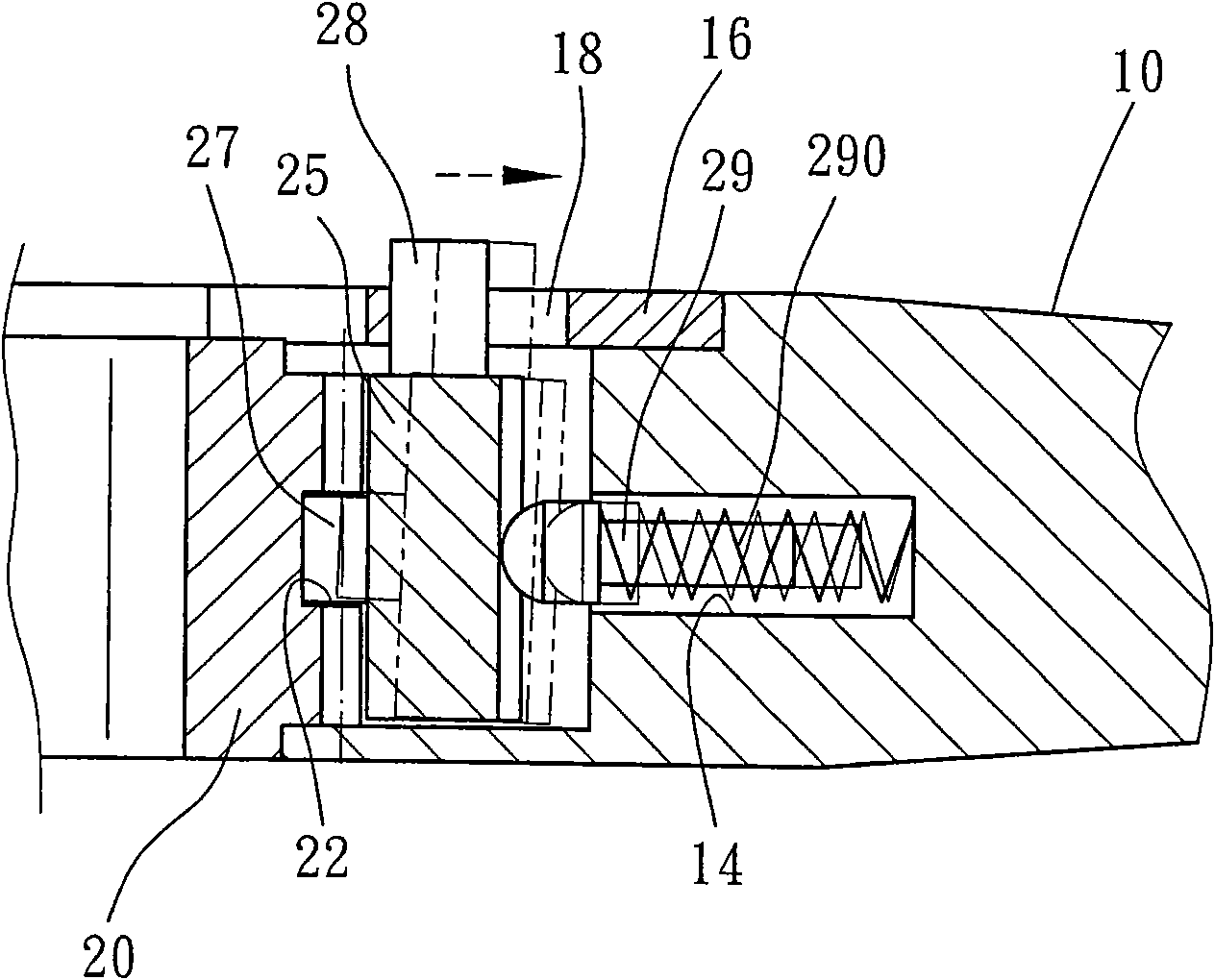
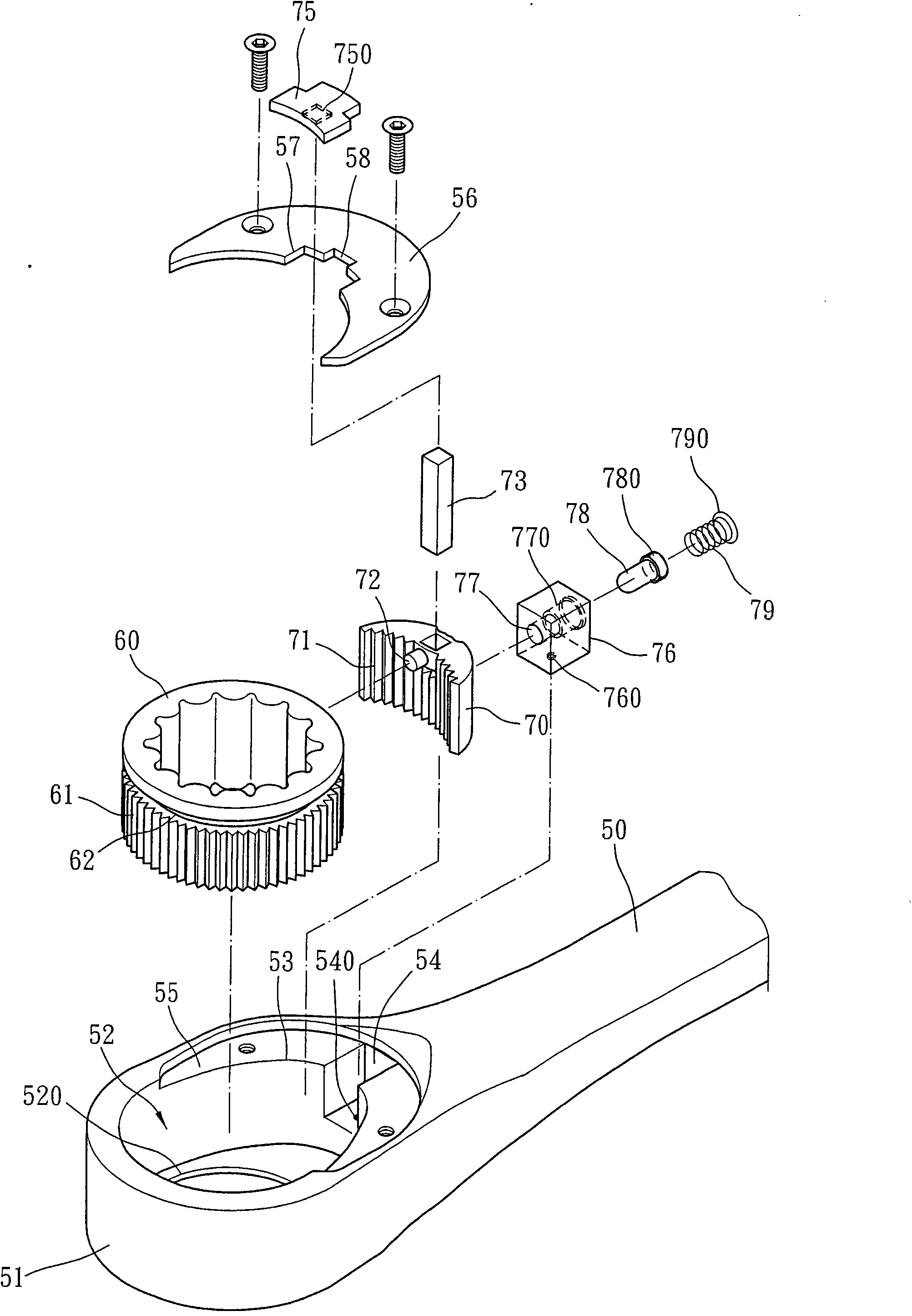
[0058] Ratchet wrench structure of the present invention, as Figure 3 to Figure 5 As shown, it includes a pull lever 50, a set wheel 60 with a nested nut and a stopper 70 for steering the turn of the set wheel 60;

[0059] At least one of the two ends of the lever 50 has a head 51, and the head 51 is formed with a hollow wheel groove 52 for accommodating the aforementioned fitting wheel 60, and the bottom edge of the wheel groove 52 is formed with a groove for the fitting wheel 60 to stick against. The abutting edge 520 and the head 51 form a dial groove 53 on the periphery of the wheel groove 52 adjacent to the lever 50. The dial groove 53 is used for accommodating the aforementioned stopper 70, and the head 51 is formed on the inner wall of the dial groove 53. An accommodating groove 54 extending toward the trigger rod 50 is formed, a recessed positioning hole 540 is formed on the bottom surface of the accommodating groove 54, and a recessed portion 55 is formed on the top ...


PUM


Abstract

A replacement structure of a ratchet wrench comprises a wrench rod, wherein at least one of the two ends of the wrench rod is provided with a head part; the head part is provided with a hollow pulley groove the bottom edge of which is provided with a butting edge; the head part is provided with a fork groove at the periphery of the pulley groove adjacent to the wrench rod; the head part is provided with a containing groove at the inner wall surface of the fork groove and the top surface of the head part is locked with a cover plate; a registration wheel is arranged on the butting edge of the pulley groove of the head part, the outer edge of the registration wheel is provided with a plurality of ratchets, and a position adjacent to the top edge, on the outer edge of the registration wheel is provided with a spacing ring groove; a brake pad is arranged in the fork groove of the head part and is provided with the plurality of the ratchets for braking the registration wheel in an engaged mode; the middle section adjacent to the top edge, of the brake pad is provided with a limit bump corresponding to the spacing ring groove; the top surface of the brake pad utilizes a connecting rod to fix zipper pulls which are attached to and abutted against the top surface of the cover plate to move; and the brake pad is provided with a fixed seat in the containing groove of the head part. The structure in the invention can enhance labor-saving performance and stationarity of the movement of the brake pad, enables the replacement of the registration wheel to be more smooth and convenient, enhances the structure strength, prolongs the service life and prevents component loss.

Description

technical field [0001] The invention relates to a ratchet wrench replacement structure. Background technique [0002] Ratchet wrench is a kind of hand tool that can act in one direction. It is used to selectively control the torsion effect of one-sided movement and idling on the other side by a matching wheel for holding nuts or bolts and a catch. The problem of constantly taking off the wrench tool and re-engaging it again is to improve the convenience and speed of the hand tool operation. However, in the traditional ratchet wrench, the matching wheel used to catch the nut or bolt is a single size specification. Set on the heads at both ends of the ratchet wrench, and such a design will make the ratchet wrench only suitable for one or two sizes, so users must prepare ratchet wrenches of various specifications to meet different operating needs, which will increase The cost of consumption also increases the weight of the toolbox, which does not conform to the development dir...

Claims


Application Information

Patent Timeline
Patent Type & Authority Patents(China)
IPC IPC(8): B25B13/46B25B23/00
Inventor 朱经增
Owner 巨琩有限公司
Why Eureka
Try Eureka