
Engine lubricant passage

A lubricating oil circuit and engine technology, applied in the direction of engine lubrication, engine components, machines/engines, etc., can solve problems such as ineffective cooling of lubricating oil, high engine cylinder temperature and high oil temperature, which is not conducive to normal engine operation, etc., to achieve lubrication And good cooling effect, lower cylinder temperature and oil temperature, and compact structure

Inactive Publication Date: 2012-06-13
力帆科技(集团)股份有限公司
View PDF0 Cites 0 Cited by
  • Summary
  • Abstract
  • Description
  • Claims
  • Application Information

AI Technical Summary

Problems solved by technology

The use of internal oil passage lubrication requires the engine crankcase to have sufficient volume to accommodate the lubricating oil capacity specified by engines with different displacements, which will result in a larger engine size, which is not suitable for off-road motorcycles’ requirements for engine volume
At the same time, there are many materials required to make the engine crankcase, and the cost will increase, and the cooling effect of the lubricating oil is not obvious. The cylinder temperature and oil temperature of the engine are high, which is not conducive to the normal operation of the engine and will reduce the power of the engine. It is not suitable for Large displacement air-cooled engine

Method used


Image

  • Engine lubricant passage
  • Engine lubricant passage

Examples


Embodiment Construction

[0017] Below in conjunction with accompanying drawing and embodiment, the present invention will be further described:

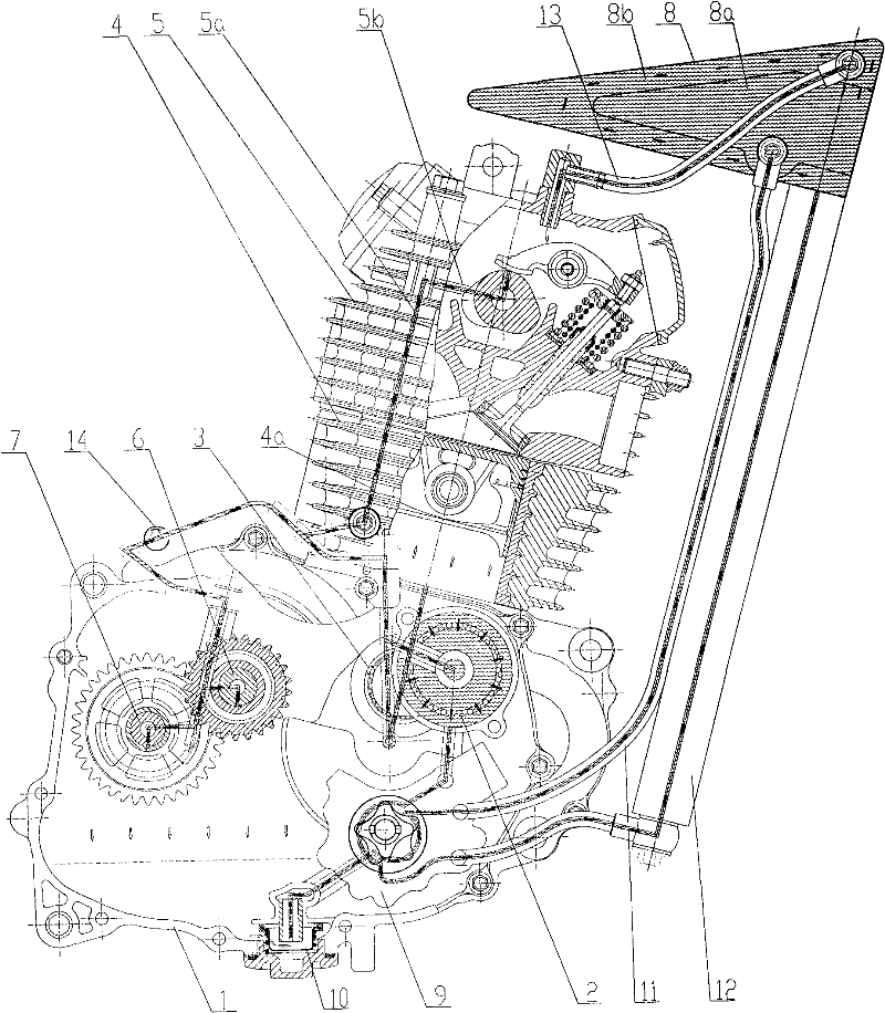
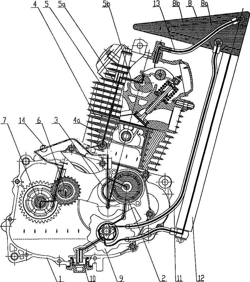
[0018] like figure 1 As shown, the engine lubricating oil is routed through crankcase 1, oil filter 2, crankshaft needle roller 3, cylinder block 4, cylinder head 5, main shaft 6, secondary shaft 7, external oil tank 8, oil pump 9, primary oil filter 10. The first outer oil pipe 11 , the second outer oil pipe 12 , the third outer oil pipe 13 and the tee outer oil pipe 14 are formed, wherein crankcase covers are installed on both sides of the crankcase 1 and are installed at the bottom of the crankcase 1 A primary oil filter 10, an oil filter 2, a crankshaft needle roller 3, a main shaft 6, a secondary shaft 7 and an oil pump 9 are also installed inside the crankcase 1. A cylinder block 4 is arranged on the top of the crankcase 1 , and a cylinder head 5 is mounted on the cylinder block 4 . The transmission structure and working principle in the engine are t...


PUM


Abstract

The invention relates to an engine lubricant passage. An oil inlet of a first cavity of an oil pump is communicated with an oil outlet of an once oil filter, an oil outlet of the first cavity of the oil pump is communicated with an oil inlet of an external oil tank, a first oil outlet of the external oil tank is communicated with an oil inlet of a second cavity of the oil pump, a second oil outlet of the external oil tank is communicated with an external oil inlet of a cylinder head, an oil outlet of the second cavity of the oil pump is communicated with an oil inlet of an oil filter, a crankcase cover oil passage communicated with an oil outlet of the oil filter is divided into two passages, one passage is communicated with an oil inlet passage of a crank roller pin, the other passage isconnected with an oil inlet of an external three-way oil pipe, a first oil outlet of the external three-way oil pipe is communicated with oil holes of a main shaft and a secondary shaft, and a secondoil outlet of the external three-way oil pipe is communicated with a camshaft oil channel. The invention not only achieves the purpose of lubricating an engine, but also can obviously reduce the cylinder temperature and the oil temperature of the engine, improves engine operating conditions and increases engine power.

Description

technical field [0001] The invention belongs to the technical field of engine lubrication, and in particular, particularly relates to an engine lubricating oil cooling system on a motorcycle. Background technique [0002] All general motorcycle engines store the lubricating oil of the lubricating and cooling system in the engine crankcase. The oil pump in the crankcase transports the lubricating oil through the various oil passages inside the engine, respectively, to the crankshaft needle roller → cylinder bore, piston ; Cam and rocker arm or rocker arm and push rod of cylinder head → lower rocker arm and cam; each rotating part of main and auxiliary shafts; bearings; purpose of the engine. The use of internal oil channel lubrication requires the engine crankcase to have enough volume to accommodate the lubricating oil capacity specified by engines of different displacements, which will result in a larger engine volume, which is not suitable for off-road motorcycles. At th...

Claims


Application Information

Patent Timeline
Patent Type & Authority Patents(China)
IPC IPC(8): F01M5/00F01M1/04
Inventor 田亚平程志明
Owner 力帆科技(集团)股份有限公司
Learn More