Combined oscillatory flow heat pipe with evaporation and heat exchange connecting section

An oscillating flow heat pipe and evaporation heat exchange technology, applied in the field of heat transfer, can solve the problems of not being able to meet the use requirements, increase the heat dissipation area of ​​the heat pipe, etc., and achieve the effect of improving heat transfer capacity, increasing heat transfer capacity, and prolonging heat transfer distance

Inactive Publication Date: 2011-12-28
NORTH CHINA ELECTRIC POWER UNIV (BAODING)
View PDF4 Cites 1 Cited by
  • Summary
  • Abstract
  • Description
  • Claims
  • Application Information

AI Technical Summary

Problems solved by technology

[0003] The oscillating flow heat pipe is a high-efficiency heat transfer element, but its heat transmission distance is usually not more than 1 to 2 meters; at the same time, in many occasions where the oscillating flow heat pipe is used for heat dissipation of the heating body, it is often required to increase the heat dissipation area of ​​the heat pipe, and Only using a single heat pipe will not meet the requirements of use

Method used


Image

  • Combined oscillatory flow heat pipe with evaporation and heat exchange connecting section
  • Combined oscillatory flow heat pipe with evaporation and heat exchange connecting section
  • Combined oscillatory flow heat pipe with evaporation and heat exchange connecting section

Examples


Embodiment Construction

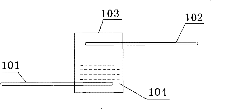
[0023] image 3 , Figure 4 , Figure 5 It is a schematic diagram of an embodiment of the present invention.

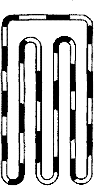
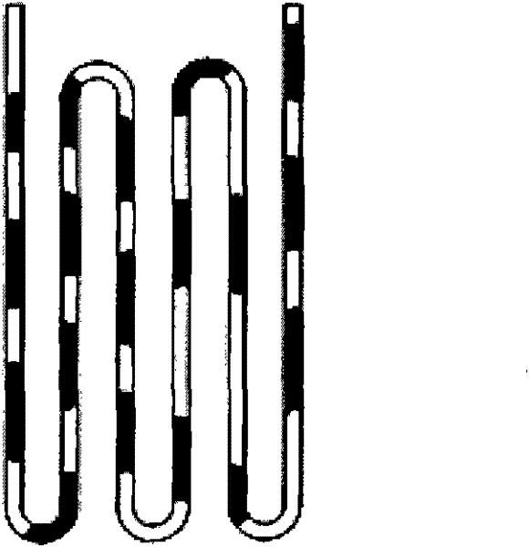
[0024] image 3 It is a schematic diagram of an oscillating flow heat pipe combination unit. like image 3 As shown, the oscillating flow heat pipe assembly unit is composed of a primary oscillating flow heat pipe 101, a secondary oscillating flow heat pipe 102, and an evaporation heat exchange connection section 103. The evaporation heat exchange connection section 103 is a vertical airtight container, and the container is filled with a working fluid 104 after vacuuming. After sealing, one end of the primary oscillating flow heat pipe 101 is placed in the evaporating heat exchange connecting section 103, and the primary oscillating flow heat pipe 101 is horizontally fixed on the lower part of the evaporating heat exchanging section 103, and one end of the secondary oscillating flow heat pipe 102 is placed in the evaporating heat exchange connecting section 103. ...


PUM


Abstract

The invention belongs to the field of heat transfer, in particular to a combined oscillatory flow heat pipe with an evaporation and heat exchange connecting section. In the invention, a condensation end of a primary oscillatory flow heat pipe and an evaporation end of a secondary oscillatory flow heat pipe are both arranged in an evaporation and heat exchange connecting section and respectively, horizontally and fixedly connected to the lower part and the upper part of the evaporation and heat exchange connecting section; the evaporation and heat exchange connecting section is internally vacuumized, filled with a working solution and then sealed; the working solution immerses the condensation end of the primary oscillatory flow heat pipe to form an oscillatory flow heat pipe combination unit, and 1-3 stages of oscillatory flow heat pipe combination units are connected in series to form the combined oscillatory flow heat pipe with the evaporation and heat exchange connecting section; and the primary and the secondary oscillatory flow heat pipes of the oscillatory flow heat pipe combination unit can also be formed by connecting 2-5 oscillatory flow heat pips in parallel. The purposeof prolonging a heat transmission distance is achieved through the serial combination of the oscillatory flow heat pipes, and the purpose of expanding the heat radiating area is achieved through a parallel combination, thus the heat transmission capacity of the oscillatory flow heat pipes is obviously improved. The invention is suitable for the fields of high-efficiency compact heat exchangers, industrial afterheat recovery, solar energy utilization, and the like.

Description

technical field [0001] The invention belongs to the field of heat transfer, in particular to a combined oscillating flow heat pipe with an evaporation heat exchange connection section. Background technique [0002] The oscillating flow heat pipe is a high-efficiency heat pipe developed in the past ten years in the world (H.Akachi: Looped Capillary Tube Heat Pipe, Proceedings of 71st General Meeting Conference of JSME, Vol.3, No.940-10, 1994 ). The oscillating flow heat pipe (also known as the pulsating heat pipe) is a serpentine pipeline bent by a long capillary tube. It consists of several thin straight pipes and several elbows, and is divided into three parts: heating section, condensation section and heat insulation section. According to the difference of its circulatory system, it can be divided into the loop type (Looped) with the head and tail connected into a closed loop (Looped). figure 1 Shown) and the unlooped (Unlooped) (such as figure 2 shown) two. Its worki...

Claims


Application Information

Patent Timeline
Patent Type & Authority Patents(China)
IPC IPC(8): F28D15/02
CPCF28D15/0266F28D15/0275
Inventor 冼海珍杨勇平刘登瀛杜小泽
Owner NORTH CHINA ELECTRIC POWER UNIV (BAODING)
Why Eureka
Try Eureka