

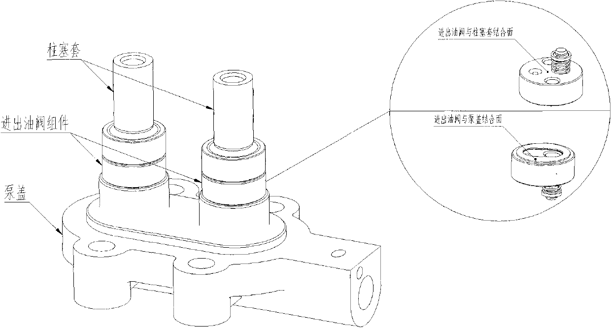
Device for detecting tightness of two junction surfaces between oil inlet/outlet valve and pump cover and plunger sleeve
A technology of oil inlet and outlet valves and testing equipment, which is applied in the direction of liquid tightness measurement using liquid/vacuum degree, which can solve the problems of low production efficiency, great influence on test results, and high labor intensity, and achieve high production efficiency and labor Effects with low intensity and high degree of automation
- Summary
- Abstract
- Description
- Claims
- Application Information
AI Technical Summary
Problems solved by technology
Method used
Image

Examples
Embodiment Construction
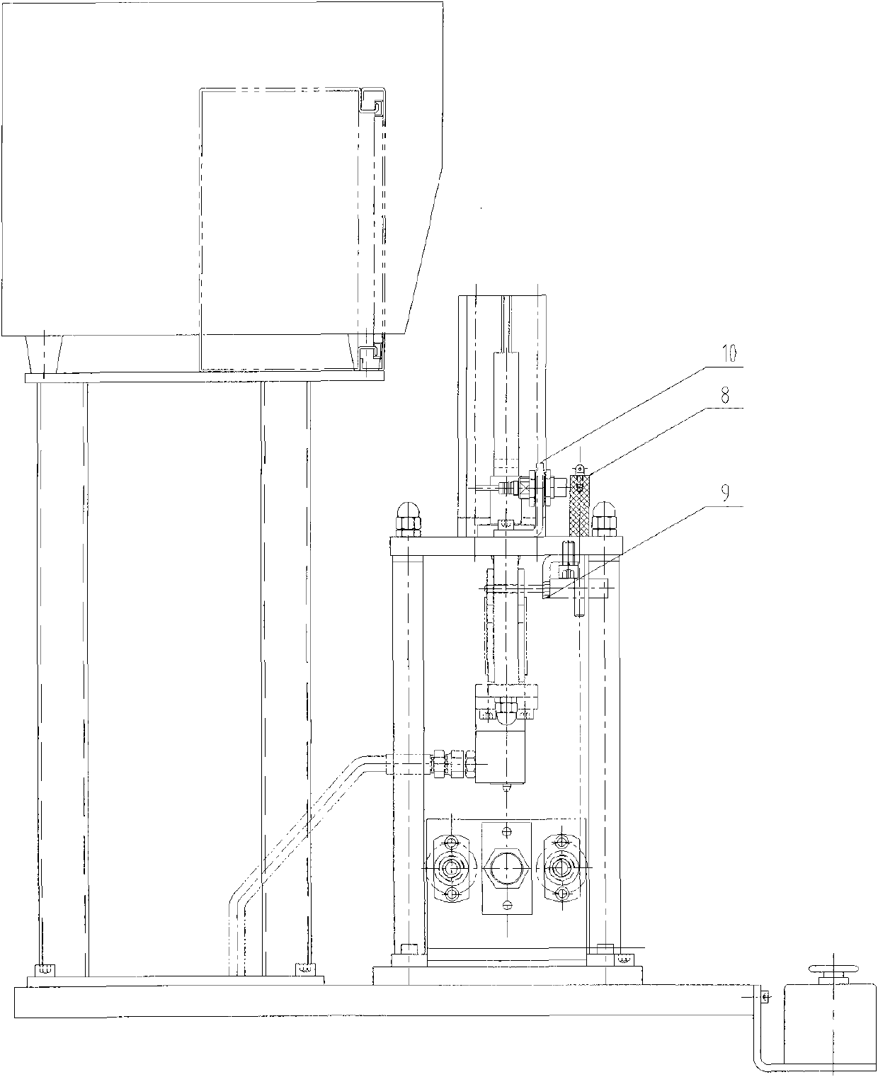
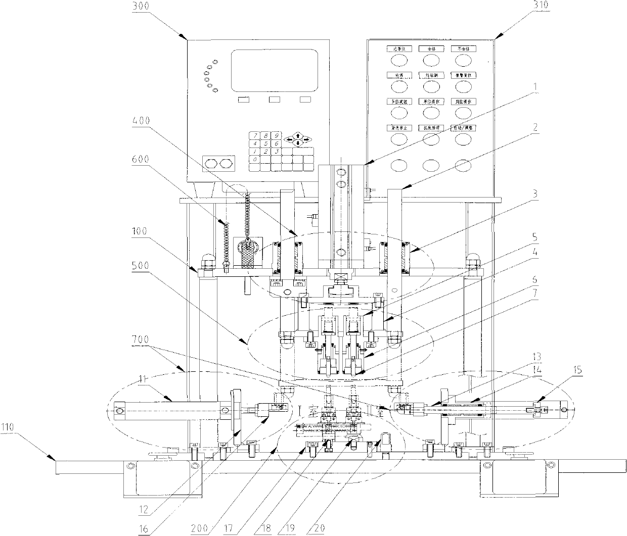
[0017] Such as Figure 2~3 The shown oil inlet and outlet valve and the pump cover and the sealing degree detection equipment of the joint surface with the plunger sleeve include: frame, bed and pneumatic and detection control system, which is characterized in that it also includes fixtures, two-station automatic feeding pneumatic Sliding table, flexible blockage detection device, shutdown safety protection device, automatic feeding device, all devices are installed on the frame and bed; the two-station automatic feeding pneumatic sliding table is composed of three-position cylinder 1, guide rod 2, Guide sleeve 3 and slide bracket 4 are formed. The flexible occlusion detection device is composed of an upper body 5 of the occlusion head, a lower body 6 of the occlusion head, and a flexible guide shaft 7 . Shutdown safety protection device is made up of bearing pin 8, support 9, latch confirming device 10. Automatic feeding device is made up of cylinder 11, support 12, guide r...
PUM
 Abstract
Description
Claims
Application Information