

Full-function word bending machine
A font bending machine and full-function technology, applied in the field of full-function font bending machines, can solve problems such as inability to process, achieve the effects of saving workshop space, reasonable equipment structure, and avoiding cost increases
- Summary
- Abstract
- Description
- Claims
- Application Information
AI Technical Summary
Problems solved by technology
Method used
Image

Examples
Embodiment 1
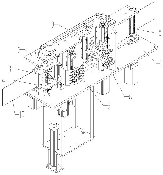
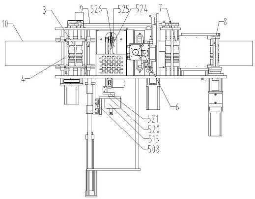
[0042] Such as Figure 1-2 As shown, a full-featured letter bending machine includes a frame on which a first feeding device 3, a milling device 5, a planing device 6, a second feeding device 7 and a bending device are sequentially arranged according to the direction of the material 10 The device 8, the first feeding device 3 and the second feeding device 7 are connected through a transmission device 9, and a feeding guide device 4 is provided on the frame near the first feeding device 3.
[0043] The frame includes a lower wallboard 1, and an upper wallboard 2 is arranged in parallel at a certain distance above the lower wallboard 1.
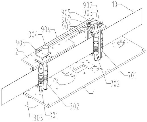
[0044] Such as Figure 3-4 As shown, the first feeding device 3 includes a first feeding roller 301 and a second feeding roller 302 , the first feeding roller 301 and the second feeding roller 302 are located between the lower wallboard 1 and the upper wallboard 2 and are rotatably connected thereto.
[0045] A feeding motor 303 is fixedly in...
Embodiment 2
[0127] The copper roller arc bending assembly described in Embodiment 1 above can be replaced by a steel arc bending assembly.
[0128] Such as Figure 19 As shown, the steel arc bending assembly includes a second arc bending outer casing 815, the lower part of the second arc bending outer casing 815 is detachably fixed to the connecting shaft 802, and the second arc bending outer casing 815 is coaxially provided with a second arc bender 816 , the top of the second arc bender 816 is detachably fixed to the upper connecting plate 806 through the mounting block 809, and the second arc bender 816 is provided with a second feeding hole 8161 for the material 10 to pass through.
[0129] With this design, the copper roller bending assembly and the steel bending assembly are easy to replace. The copper roller bending assembly can process aluminum profiles, folded aluminum and flat aluminum and other materials; the steel bending assembly can process stainless steel plates, galvanized ...
PUM
 Abstract
Description
Claims
Application Information