Sealed battery and producing method therefor

A manufacturing method and airtight technology, applied in the direction of airtight accumulators, secondary batteries, battery pack components, etc., can solve the problems of electrolyte leakage, damage, and inability to obtain the joint state, and achieve the effect of ensuring electrical continuity

Active Publication Date: 2010-12-08
日本汽车能源株式会社
View PDF4 Cites 6 Cited by
  • Summary
  • Abstract
  • Description
  • Claims
  • Application Information

AI Technical Summary

Problems solved by technology

However, when the lamination guide is connected to a member having a through-hole by laser welding or the like, if the melting caused by welding reaches the through-hole, there is no place to go for the input heat accompanying the welding at the edge of the through-hole, and the heat is concentrated.
Therefore, there is a potential problem of becoming excessively molten, causing spatter or splashing, or producing molten pits (open holes) on the part and failing to obtain a normal joining state
Therefore, especially in the case of a thin plate-shaped member having a valve mechanism, deformation or heat-induced deformation occurs, the valve does not open to the specified pressure inside the battery when the battery is misused, the battery is damaged, or conversely, the battery is normally damaged. When the valve is opened in a warm state during use, the airtightness of the sealed battery cannot be ensured, which may cause leakage of the electrolyte

Method used


Image

  • Sealed battery and producing method therefor
  • Sealed battery and producing method therefor
  • Sealed battery and producing method therefor

Examples


Embodiment 1

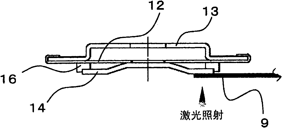
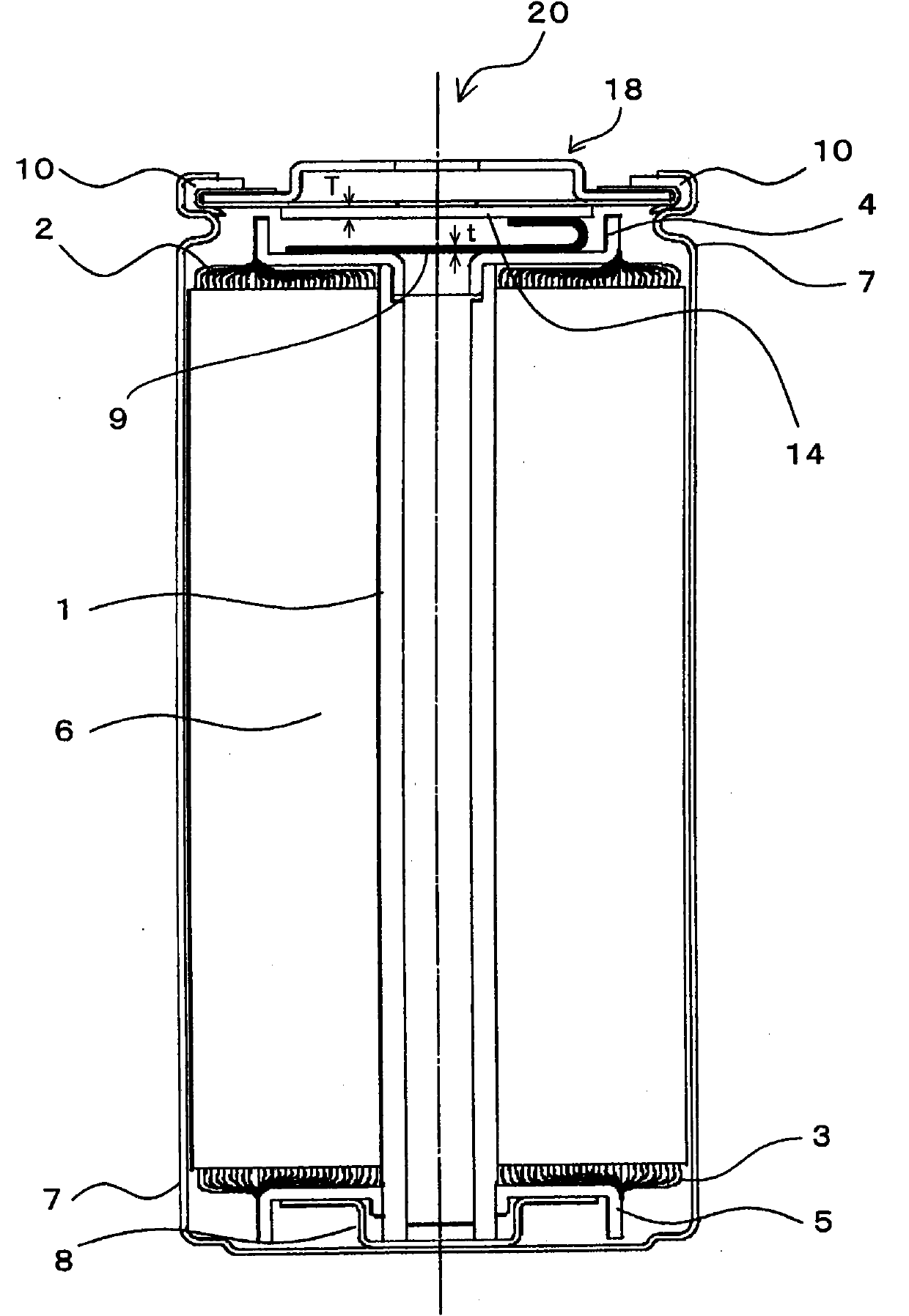
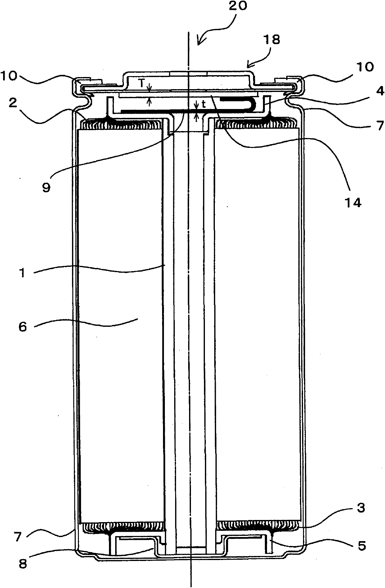
[0059] In Example 1, such as Figure 4 As shown, a connection member 14 having a thickness T of 1.0 mm is bonded to the spacer 12 of the battery cover 18 by ultrasonic waves. The stacking guide 9 (ultrasonic bonding portion 9a) is brought into contact with the side of the connecting member 14 opposite to the battery cover 18, and a laser beam is irradiated from the side of the stacking guide 9 (lower side in the figure) to connect the stacking guide 9 and the connecting member. 14 welding. YLR-2000 manufactured by IPG Corporation was used for laser oscillation, and YW-50 manufactured by Precitec Corporation was used as a processing head. The irradiation laser was set to have a focal distance of 200 mm, an output of 750 W, a beam diameter of 0.2 mm, and a scanning speed of 3 m / min. Laser irradiation was irradiated in a length of 6 mm in the width direction of the lamination guide 9, and 3 rows were irradiated at intervals of 1 mm. As a result of the irradiation, the fusion w...

Embodiment 2

[0063] In Example 2, such as Image 6 As shown, from one end of the lamination guide 9 (the side to be bonded to the connecting member 14 ) to 5 mm in full width, an ultrasonic bonding portion 9 a is formed by ultrasonic bonding to fix the thin plates to each other. The lamination guide 9 and the connecting member 14 are welded by laser irradiation. The irradiation position of the laser beam does not protrude from the end or side end of the ultrasonic bonding part 9a or the lamination guide 9, but is limited within the range of the ultrasonic bonding part 9a. The thickness T of the connecting member 14 was 1.0 mm as in the first embodiment. In terms of laser irradiation, the conditions for Example 1 only lowered the output to 650W.

Embodiment 3

[0065] In Example 3, such as Figure 7 As shown, from one end of the lamination guide 9 (the side to be bonded to the connecting member 14 ) to 3 mm over the entire width, an ultrasonic bonding portion 9 a is formed by ultrasonic bonding to fix the thin plates to each other. The lamination guide 9 and the connecting member 14 are welded by laser irradiation. The irradiation position of the laser beam does not protrude from the end or side end of the lamination guide 9, but protrudes from the ultrasonic bonding part 9a to the part not bonded by the ultrasonic wave, and is not limited to the position within the range of the ultrasonic bonding part 9a. The thickness T of the connecting member 14, the laser light and its irradiation conditions are the same as those in the second embodiment.


PUM

PropertyMeasurementUnit
thicknessaaaaaaaaaa
widthaaaaaaaaaa
lengthaaaaaaaaaa

Abstract

The invention provides a sealed battery which can guarantee conduction between a power generator and a cover body without generating a welding defect. A lithium ion secondary battery includes a battery container (7). The battery container (7) houses an electrode winding body, on which positive and negative electrode plates are wound via separators, together with a non-aqueous electrolytic solution. A positive electrode tab is bonded to a positive current collector ring (4) arranged at an upper side of the electrode winding body. A battery lid (18) to be a positive electrode external terminal is crimped and fixed to the battery container (7). The battery lid (18) has a diaphragm in which a cleaving valve (12) is formed. A coupling part is bonded to the diaphragm, and a stack lead (9) with a plurality of thin plates being laminated is bonded to the coupling part. In the stack lead (9), a total sum t of thicknesses of the thin plates is not more than a thickness T of the coupling part. Melting from the stack lead (9) to the coupling part by laser irradiation is optimized.

Description

technical field [0001] The present invention relates to a sealed battery and a method for manufacturing the sealed battery, in particular to: a power generating body equipped with a positive electrode, a negative electrode, and a separator; an electrolyte for soaking the generating body; and a bottomed container for accommodating the generating body and the electrolyte. A sealed battery and a method for manufacturing the sealed battery. Background technique [0002] In a conventional sealed battery, a power generator including a positive electrode, a negative electrode, and a separator is housed in a container together with an electrolyte solution, and the container is sealed by a lid. In order to lead out the electric power from the power generator to the outside of the battery, the power generator and the cover are connected by an electrically conductive lead. Usually, the guide is housed in the container in a bent state. In the case of such a sealed battery, it is neces...

Claims


Application Information

Patent Timeline
Patent Type & Authority Applications(China)
IPC IPC(8): H01M10/34H01M50/528H01M50/536H01M50/538
CPCH01M2/263Y02E60/122H01M10/0525H01M2/0413H01M10/0587Y02E60/10H01M50/171H01M50/538H01M50/536
Inventor 中井贤治多田明德青田欣也松本洋
Owner 日本汽车能源株式会社
Why Eureka
Try Eureka