Device for electrochemical treatment, locally in particular, of a conductor substrate

a technology for electrochemical treatment and conductor substrates, applied in the direction of electrolytic coatings, surface reaction electrolytic coatings, anodization, etc., can solve the problems of device flow risk, localized metallic retouching, wear, scratching or corrosion, etc., to avoid short-term shutting down of devices and avoid variations in the rotation of pumps

Active Publication Date: 2015-07-02
DALIC
View PDF6 Cites 2 Cited by
  • Summary
  • Abstract
  • Description
  • Claims
  • Application Information

AI Technical Summary

Benefits of technology

[0035]Using an FR device ensures a clean and pressure-regulated supply of air, which makes it possible to avoid briefly shutting down the device (to await the return to an appropriate temperature).
[0036]Moreover, the use in the device of a flowmeter and of a brushless motor for the pumps makes it possible to ensure a controlled and regular flow at the electrolyte inlet and outlet, because the absence of brushes makes it possible to avoid variations in the rotation of the pump.

Problems solved by technology

In these industries and in many others, including plastics and mechanical engineering, it also happens that metallic surfaces or parts suffer wear, scratching, scuffing or corrosion that justify such localized metallic retouching.
These devices nevertheless are still subject to risks of flow during treatment, related to the quality of the seal provided by the seals or during cleaning after treatment (in the case of gels), and risks linked to the uniformity of the treatment.
Accordingly, leaks of electrolyte, notably during movement of the device over the substrate, represent a real danger for the surrounding areas that must not be treated and for the operator, because of the often corrosive nature of the electrolytes used.
However, this device has disadvantages in that the same tool cannot be used for different surfaces to be treated, such as plane surfaces and surfaces of convex shape.
Moreover, this device does not always make it possible to set accurately or to maintain the electrolyte flow rate that is however a decisive characteristic for the quality of the electrochemical treatment.

Method used


Image

  • Device for electrochemical treatment, locally in particular, of a conductor substrate
  • Device for electrochemical treatment, locally in particular, of a conductor substrate
  • Device for electrochemical treatment, locally in particular, of a conductor substrate

Examples


Embodiment Construction

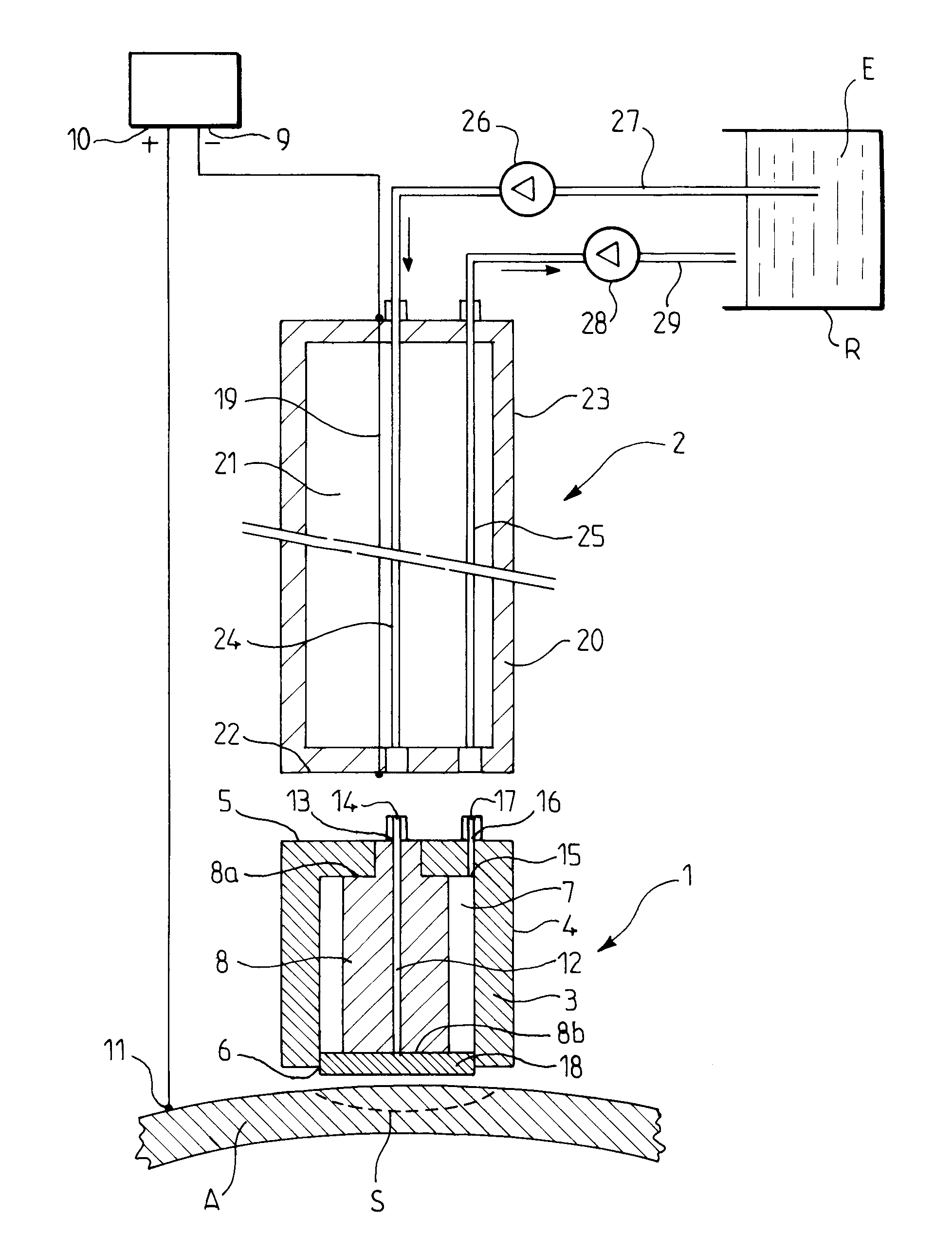
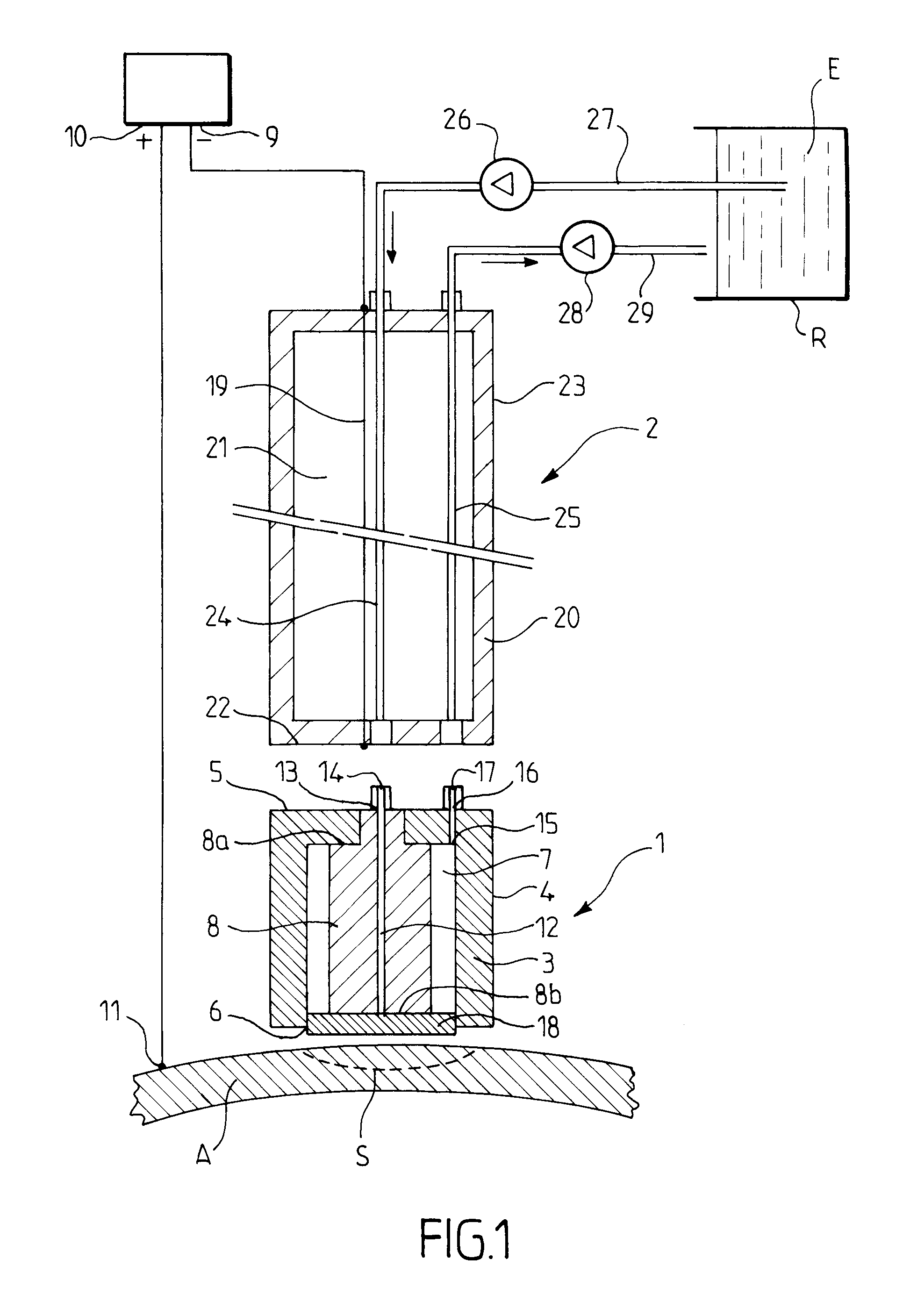
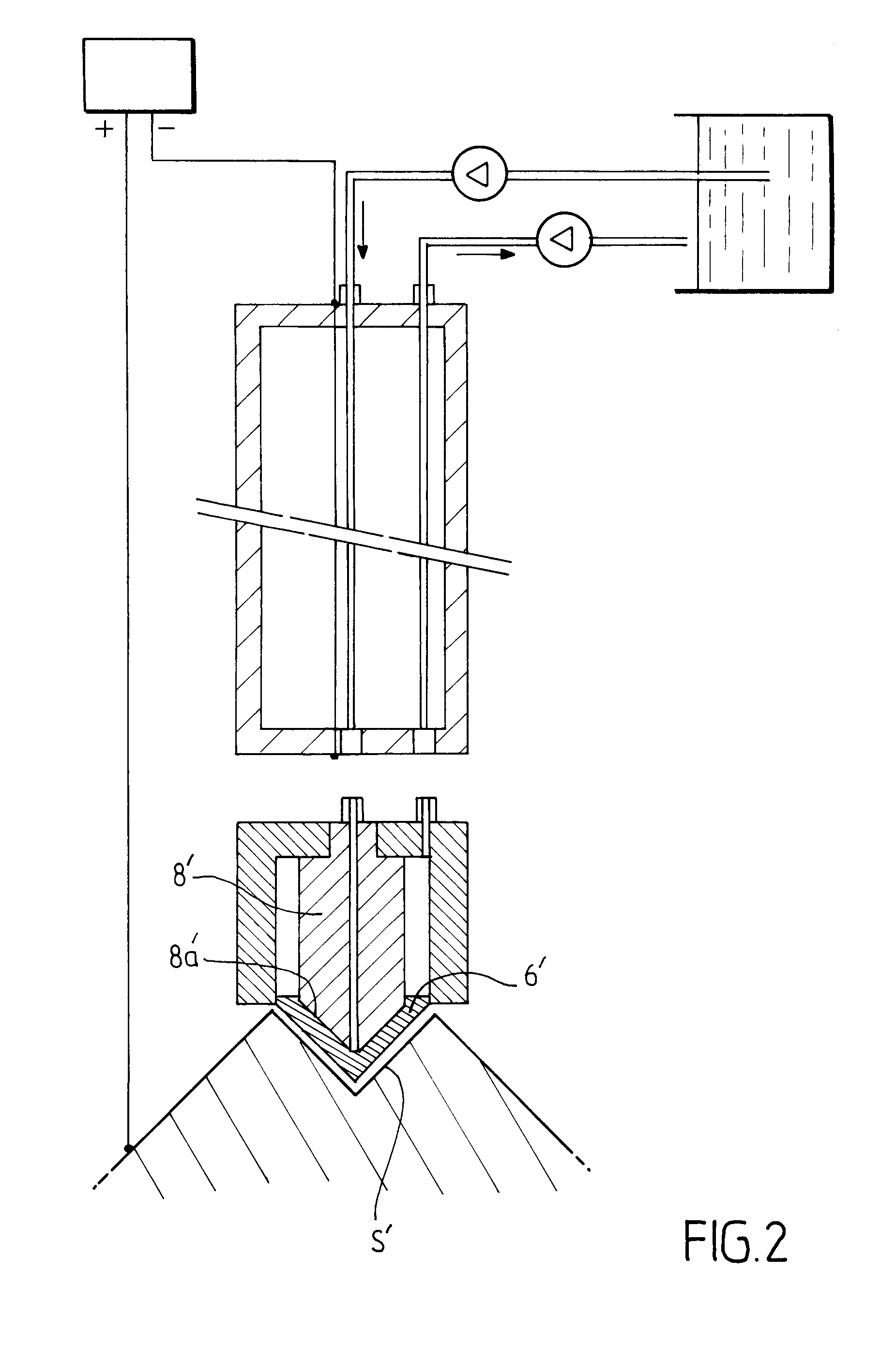
[0043]FIG. 1 represents a device in accordance with the invention for anodic oxidation enabling preparation of a surface S of an aluminum part A, before gluing.

[0044]The device includes a head 1 and a handle 2.

[0045]The head 1 includes a casing 3 having a lateral wall 4, a rear wall 5 and a front opening 6 opposite the rear wall 5. This casing defines an internal space 7 in which is housed a cathode 8 facing the opening 6.

[0046]The cathode 8 has a front face 8b in contact with a plane absorbent material pad 18 and may, for example, have a circular, square or rectangular cross section, the usable cathode area being variable from a few mm2 to a few cm2.

[0047]The cathode 8 is moreover retained in the space 7 by any means and notably by fixing its rear face 8a at at least two points to the rear wall of the casing 3. On the other hand, the cathode 8 has dimensions such that, on the one hand, it delimits with the interior face of the lateral wall 4 of the casing 3 a continuous peripheral ...


PUM

PropertyMeasurementUnit
temperatureaaaaaaaaaa
angleaaaaaaaaaa
angleaaaaaaaaaa

Abstract

The invention relates to a device for electrochemical treatment, locally in particular, of a conductor substrate by movement across said substrate, which can be used in every position, including a head, a shaft, an electrolyte inlet and outlet each including a flexible pipe, and two peristaltic pumps mounted on the electrolyte inlet and outlet, the head of said device being removable from said shaft, the pumps being connected to a brushless motor and the device also comprising a flowmeter for adjusting and controlling the flow in the inlet portion of said head.

Description

BACKGROUND[0001]1. Field of the Invention[0002]The subject matter of the present invention is a device for electrochemical treatment, locally in particular, of a conductor substrate by movement over said substrate, usable in any position.[0003]2. Description of the Related Art[0004]Such a device notably enables production of metallic coatings formed electrochemically and localized surfacing or touching up on metallic surfaces. In the automotive, aeronautical or rail industry, it frequently happens that surfaces must be prepared before assembly or before another surface treatment. In these industries and in many others, including plastics and mechanical engineering, it also happens that metallic surfaces or parts suffer wear, scratching, scuffing or corrosion that justify such localized metallic retouching.[0005]Such electrochemical treatment devices are already known, such as for example devices of the pad type, as well as devices employing electrolyte circulation chambers or cells ...

Claims


Application Information

Patent Timeline
Patent Type & Authority Applications(United States)
IPC IPC(8): C25D21/10C25D11/02
CPCC25D11/02C25D21/10C25D5/06C25F7/00C25D11/022
Inventor CHAIX, JEAN PIERRE
Owner DALIC
Why Eureka
Try Eureka