Supercharge Your Innovation With Domain-Expert AI Agents!

Non-contact inductive switchgear and control method thereof

A non-contact sensing and switching device technology, applied in electronic switches, electrical program control, program control in sequence/logic controllers, etc., can solve problems such as insecurity, hard-to-read function characters, loss of non-contact operation, etc., to achieve Strong anti-interference ability, small sensing trigger distance and high reliability

Inactive Publication Date: 2010-12-08
金德奎
View PDF3 Cites 2 Cited by
  • Summary
  • Abstract
  • Description
  • Claims
  • Application Information

AI Technical Summary

Problems solved by technology

The advantage of this type of non-contact induction switch device is that the non-contact induction operation can prevent the spread of viruses and bacteria, and has certain safety. The disadvantage of CN 2909701Y is that the light emitting component and the receiving component are very close to the button area, and the hands need to be slow and careful. If you are not careful, you will touch the surface of the button, and there is still a chance to contact the virus, which loses the meaning of non-contact operation
The disadvantage of CN2909701Y is that the light emitting component and the receiving component are far away from the button area, which can reduce the chance of touching the button area, but the deep sensing space sunken in the surface gives people a sense of insecurity, and the function characters on the button Difficult to see from certain angles, requires a lot of space
Setting luminous indications on the surface of the induction information unit and setting sound prompts in the switch may reduce this kind of false contact, but it cannot fundamentally solve it.

Method used


Image

  • Non-contact inductive switchgear and control method thereof
  • Non-contact inductive switchgear and control method thereof
  • Non-contact inductive switchgear and control method thereof

Examples


no. 1 example

[0045] see Figure 5 The sensing information input unit 1 includes a key (or button) 11 , a surface 13 of a sensing area, and a sensing electrode 12 installed in the key 11 . The electric device 2 includes a coil 21 installed inside the button 11 of the induction information input unit 1 , a magnetic pole 23 installed on the device body 3 , a magnet 22 connected to the magnetic pole 23 , and a magnetic pole 24 is installed outside the magnet 22 . In order to make the induction area surface 13 return to its original position, a spring 4 is installed between the inner end of the induction information input unit 1 equipped with the coil 21 and the magnetic pole 23 . The spring 4 can also be placed at an appropriate position between the device body 3 as a fixed part and its fixed connection, and the sensory information input unit 1 as a moving part. The power output end of the electric device in this embodiment is a coil. The connecting wires of the coil 21 and the induction ele...

no. 2 example

[0048] see Figure 7 The sensing information input unit 1 includes a key 11 , a sensing area surface 13 , and a sensing electrode 12 installed in the key 11 . The electric device 2 includes a coil 21 installed inside the key 11 of the induction information input unit 1 and a magnet 22 installed on the device body 3 . The panel 5 covers the device body 3 .

[0049] see Figure 8 , its working principle is basically the same as that of the first embodiment. When in use, the human hand gradually approaches the surface of the sensing area of ​​the rocker-type sensing information input unit. When the distance between the human hand and the sensing area surface below the rocker-type sensing information input unit reaches the effective sensing trigger distance of the switch When H, the seesaw-type induction information input unit transmits the received information to the control unit, and the control unit judges the validity of the information. If it is valid, it sends an electric ...

no. 3 example

[0052] see Figure 9 The sensing information input unit 1 includes a key (or button) 11, a surface of the sensing area 13, an infrared emitting tube and a receiving tube 14 installed on the side of the key 11. The electric device 2 includes an armature 27 installed inside the key 11 of the induction information input unit 1 , a pole shoe 26 installed on the device body 3 , an iron core 25 connected to the pole shoe 26 , and a coil 21 installed on the iron core 25 . The panel 5 and the device body 3 are connected together, and may also be connected together by fasteners for ease of assembly. The device is also provided with a guide member and a spring (not shown) for resetting the surface of the sensing area.

[0053] see Figure 10 , its working principle is basically the same as that of the first embodiment, except that the sensing information input unit replaces the sensing electrodes with infrared emitting and receiving devices, and will not be repeated here.


PUM


Abstract

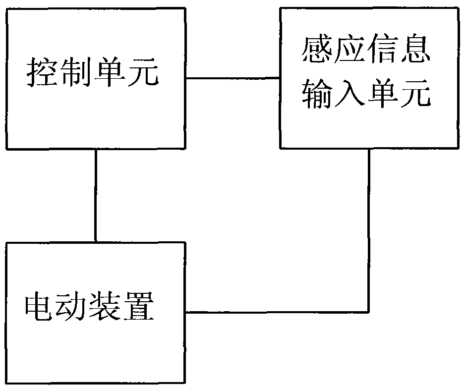
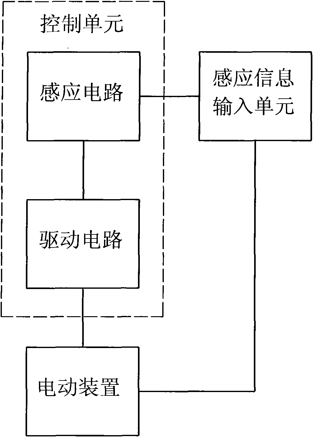
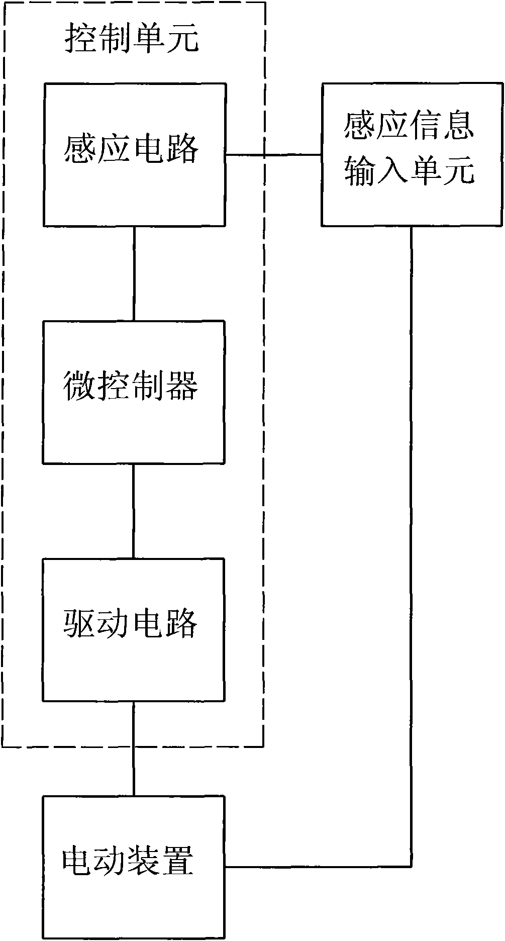
The invention relates to a non-contact inductive switchgear and a control method thereof. The switchgear comprises an inductive information input unit, an electric device and a control unit, wherein the inductive information input unit can input hand induction information in a non-contact way and is provided with an inductive signal output end; the electric device can move under the action of electric excitation and is provided with a fixed end and a power output end; the fixed end is connected with the device body; the power output end is at least connected with an induction information input unit and can at least drive the induction information input unit or components therein to move; the control unit receives an induction signal for inducing the induction information input unit and generates the electric excitation which can drive the electric device to move; a signal input end of the control unit is connected with the signal output end of the induction information input unit; and an electric excitation output end of the control unit is connected with an electric excitation input end of the electric device. When the distance from the hand to the surface of an induction region of the induction information input unit reaches an effective induction trigger distance H, the surface of the induction region instantaneously moves for a distance of delta distance in the direction away from the hand so as to prevent the hand from touching the surface of the induction region.

Description

technical field [0001] The invention relates to a switch device, in particular to a non-contact induction switch device and a control method thereof. Background technique [0002] Mechanical key switches and push button switches are widely used in various known switch devices. Existing electronics, electrical equipment and electrical equipment such as elevator buttons and wall switch buttons belong to this type of switch device. These switchgears need to be touched by human hands and exert a certain force to realize the operation, which is very unhygienic, and the switchgears used by many people, especially in public places, are easy to spread viruses and bacteria. The spread of the SARA virus in 2003 has given us a warning, and the current spread of influenza A (H1N1) around the world makes people urgently need a non-contact inductive switch device. [0003] The disclosed non-contact induction switch device, such as CN 2619415Y non-contact / contact double-function elevator ...

Claims


Application Information

Patent Timeline
IPC IPC(8): H03K17/945G05B19/04
Inventor 金德奎
Owner 金德奎
Features
  • R&D
  • Intellectual Property
  • Life Sciences
  • Materials
  • Tech Scout
  • Unparalleled Data Quality
  • Higher Quality Content
  • 60% Fewer Hallucinations
Learn More