Brake system and method for operating a brake system

A braking system and master brake cylinder technology, applied in electric braking systems, brakes, electric vehicles, etc., can solve the problems of expensive and expensive electronic devices, and achieve the effect of low cost

Inactive Publication Date: 2010-12-08
ROBERT BOSCH GMBH
View PDF3 Cites 15 Cited by
  • Summary
  • Abstract
  • Description
  • Claims
  • Application Information

AI Technical Summary

Problems solved by technology

But such brake-by-wire braking systems require expensive electronics and are therefore expensive

Method used


Image

  • Brake system and method for operating a brake system
  • Brake system and method for operating a brake system
  • Brake system and method for operating a brake system

Examples


Embodiment Construction

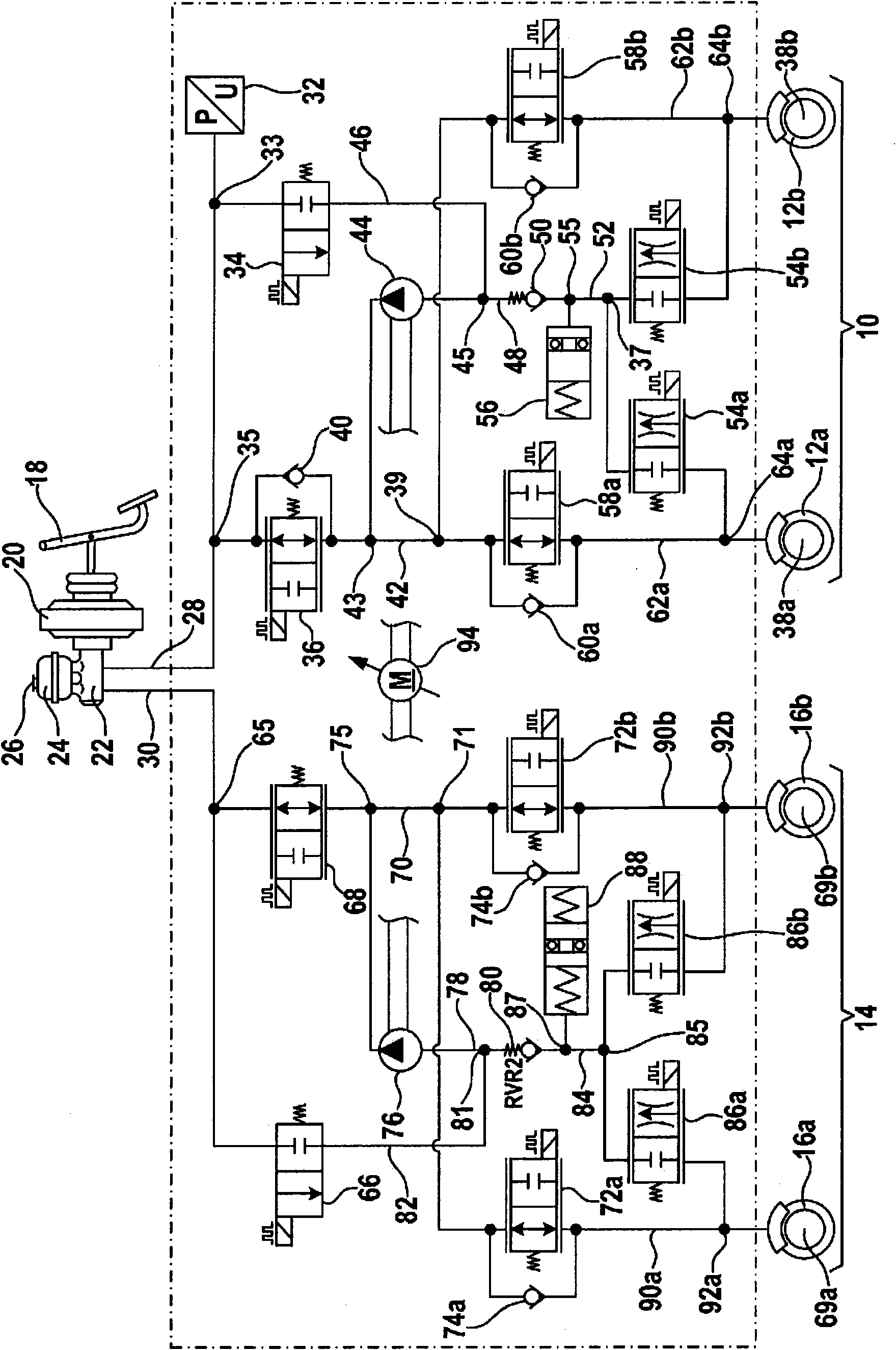
[0029] figure 1 A circuit diagram of a first embodiment of the brake system is shown.

[0030] exist figure 1The brake system shown in is designed as a dual-piston system by way of example. The braking system comprises a front brake circuit 10 for braking the front wheels 12a and 12b and a rear brake circuit 14 for braking the rear wheels 16a and 16b. However, the example shown is not limited to this distribution of the wheels 12a, 12b, 16a and 16b. Of course, this example can also be applied to an embodiment in which the wheels 12a and 12b are the rear wheels of the vehicle and the wheels 16a and 16b are the front wheels of the vehicle. The wheels 12a and 12b and the wheels 16a and 16b can also be two pairs of wheels arranged on two different sides of the vehicle or arranged diagonally on the vehicle.

[0031] It is hereby clearly stated that the figure 1 The braking system shown in is not limited to a fixed number of four wheels 12a, 12b, 16a and 16b. Alternatively, th...


PUM


Abstract

The present invention relates to a brake system for a vehicle, comprising a main brake cylinder (22), which is configured to detect an actuation of a brake input element (18) and to provide a pressure signal corresponding to the actuation of the brake input element (18), and a first brake circuit (14) having a first wheel brake cylinder (69a,69b), which is configured to exert a force corresponding to the pressure signal onto a first wheel (16a, 16b), a first switching valve (68) disposed between the main brake cylinder (22) and the first wheel brake cylinder (69a,69b), said switching valve being configured as a separating valve, a first pump (76), and a storage chamber (88), wherein the storage chamber (88) has a storage volume on a side facing the first pump (76) in the idle state, and a first wheel outlet valve (86a,86b), which is associated with the first wheel (16a, 16b) and configured to control a brake medium flow between the first wheel cylinder (69a,69b) and the storage chamber (88). The invention further relates to a method for controlling a corresponding brake system.

Description

technical field [0001] The invention relates to a braking system for a vehicle. Furthermore, the invention relates to a method for operating a brake system for a vehicle. Background technique [0002] During regenerative braking, the vehicle is braked while the electric motor is operated as a generator. The electric drive motor of the vehicle is usually operated as a generator at this point. The electrical energy harvested in this way is stored in memory. The stored energy is preferably used later to accelerate the vehicle. The power losses that occur with conventional braking methods are reduced by the regeneration described here. In this way, the energy consumption and / or exhaust emissions of a frequently braking vehicle can be reduced. Vehicles designed to brake regeneratively are often referred to as hybrid vehicles. [0003] However, the regenerative braking should not affect the braking distance. The regenerative braking method thus places additional demands on ...

Claims


Application Information

Patent Timeline
Patent Type & Authority Applications(China)
IPC IPC(8): B60T8/48B60L7/26
CPCB60T8/4054B60T8/3655B60T8/4072B60T8/4063B60T8/266B60T8/5093B60T8/4872
Inventor G·武尔思V·梅尔M·莱布莱因W·奎兰特M·孔茨
Owner ROBERT BOSCH GMBH
Why Eureka
Try Eureka