Distillation tank

A tank body and tank cover technology, applied in the field of distillation tanks, can solve the problems of impure distillate, inconvenient cleaning, easy fouling of coils, etc., and achieve the effect of simple and convenient cleaning

Active Publication Date: 2010-12-15
爱阔特(上海)清洗设备制造有限公司
View PDF3 Cites 2 Cited by
  • Summary
  • Abstract
  • Description
  • Claims
  • Application Information

AI Technical Summary

Problems solved by technology

However, the coil generates a very high temperature after heating, so that impurities in the waste liquid are easily adsorbed near the coil. After a long time of use, the coil is prone to fouling and affects heat transfer, so that the device does not heat up when the waste liquid is heated. uniform
Th

Method used


Image

  • Distillation tank
  • Distillation tank
  • Distillation tank

Examples


Embodiment Construction

[0013] Describe in further detail below in conjunction with accompanying drawing and embodiment of the present invention:

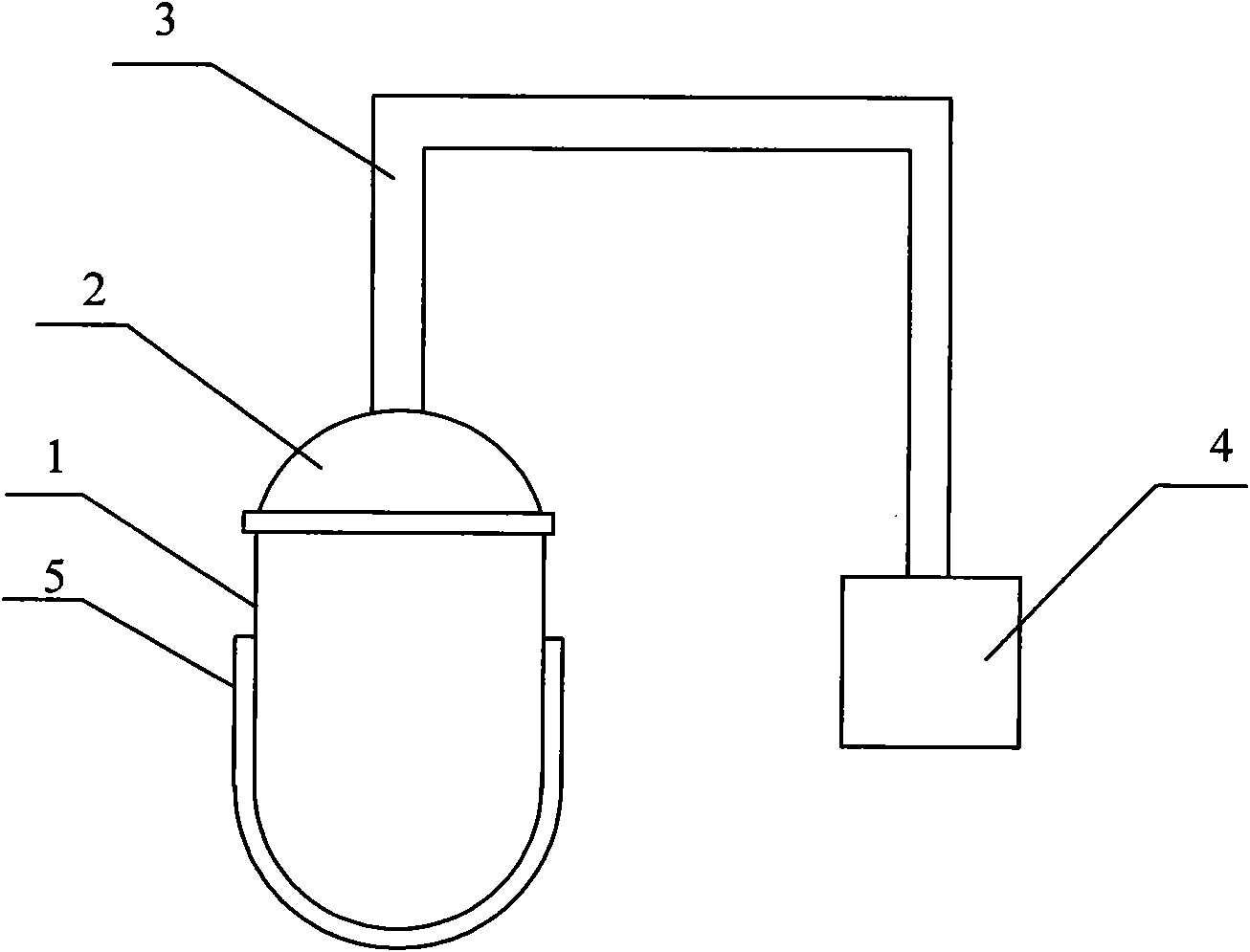
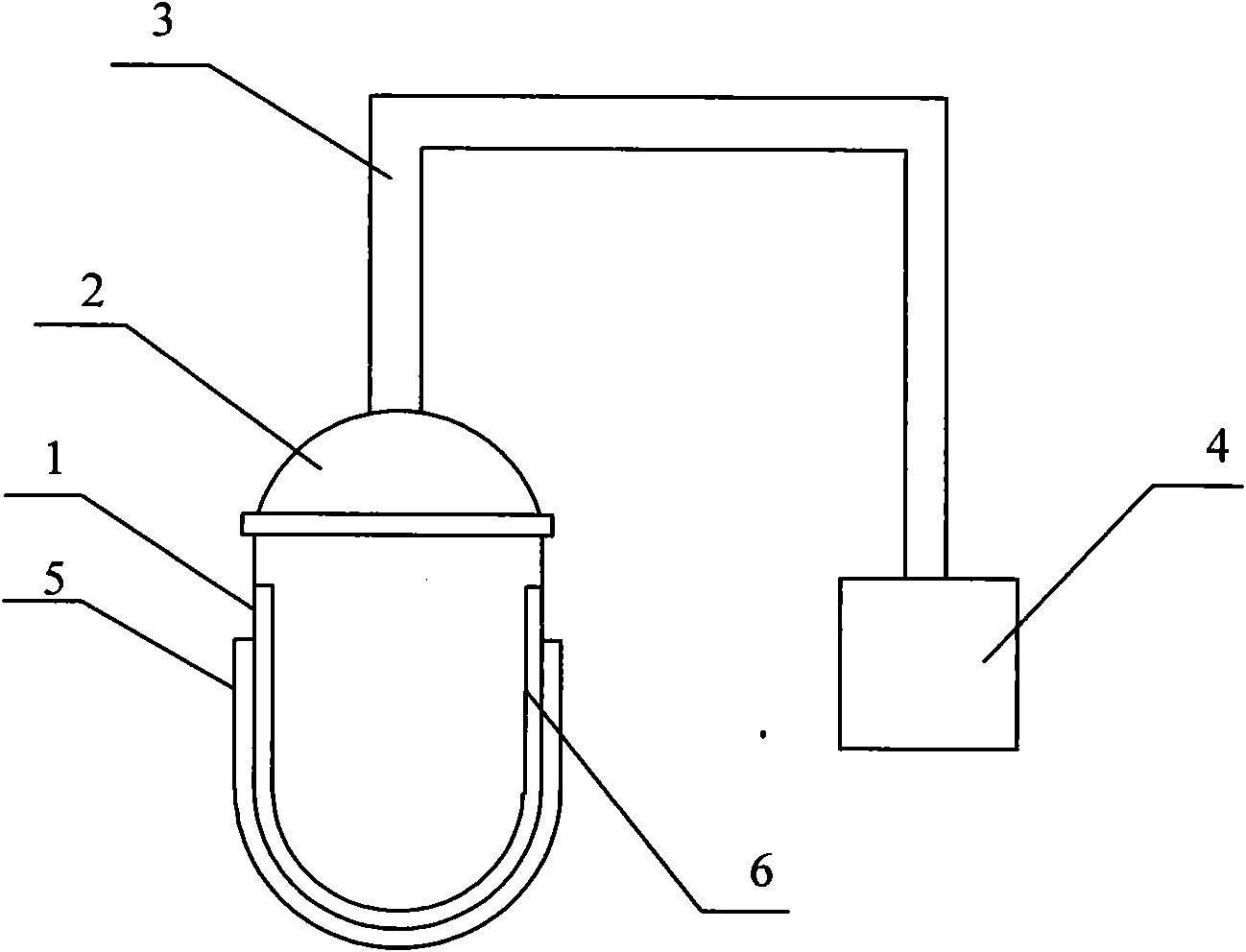
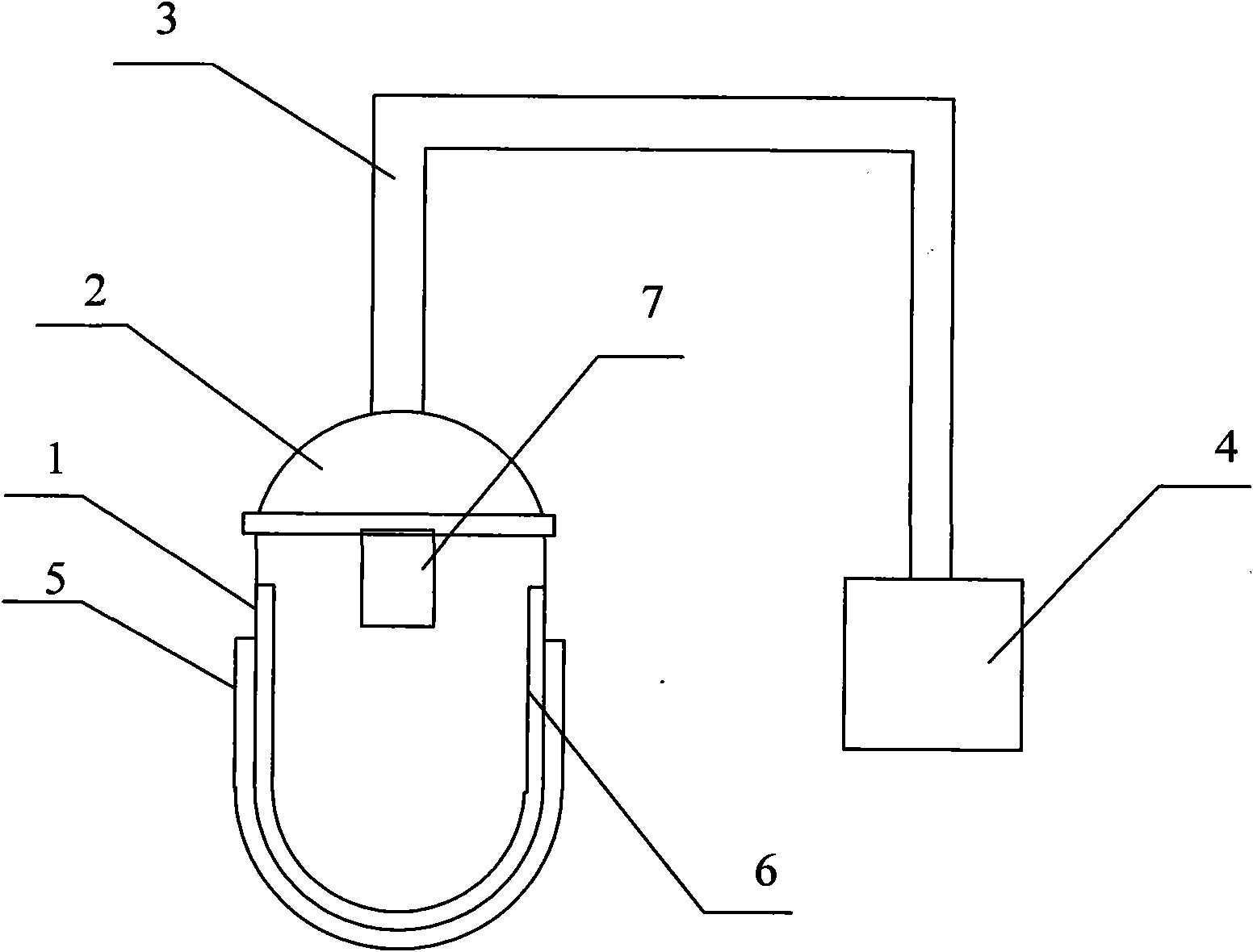
[0014] figure 1 A first embodiment of the invention is shown. Such as figure 1 As shown, the distillation tank of the present invention includes a tank body 1 and a tank cover 2. The tank cover 2 covers the tank body 1, and the inside of the whole distillation tank is in a sealed and vacuum state by means of sealing. The bottom of the tank body is set as a hollow heating interlayer 5, which is filled with heat transfer oil. By heating the heat transfer oil, the waste liquid in the distillation tank is indirectly heated. The waste liquid contains impurities, dirt, iron powder, etc. The waste liquid in the distillation tank body 1 is heated by the heat medium heat transfer oil in the distillation tank to make the distillate boil and gasify to form a distillate, which is transported to the condensation pump 4 through the delivery pipe 3 . One end of the c...


PUM


Abstract

The invention relates to a distillation device, in particular to a distillation tank. The distillation tank comprises a tank body and a tank cover, wherein the tank cover is arranged on the tank body; the bottom of the tank body is a hollow heating interlayer; heating medium heat transfer oil is filled into the hollow heating interlayer; and a distillate inside the tank body is indirectly heated by heating the heating medium heat transfer oil. The inner wall of the bottom of the tank body of the distillation tank is adhered with a layer of heat resisting thin film, the heat resisting thin film is required to be replaced regularly, and the tank body does not need cleaning. The distillation device comprises the design key point that: the bottom of the tank body adopts the hollow heating interlayer, so the distillation tank can be cleaned conveniently without disassembling equipment units. In addition, the distillation device can avoid non-cleaned dead angles, conveniently and easily cleans scales by using the heat resisting thin film and can conveniently remove dirt without a cleaning liquid.

Description

technical field [0001] The invention belongs to the technical field of industrial cleaning, in particular to a distillation tank in an industrial cleaning machine. Background technique [0002] The distillation equipment commonly used in the market is equipped with a coil in the distillation tank. The coil is hollow, and the heat medium and heat transfer oil are passed through the coil. By heating the heat medium and heat transfer oil, the distillation tank is indirectly heated. The waste liquid is heated to make the waste liquid boil and gasify, and the gasified gas becomes distillate when it is cooled, and is sent to the condenser through the transmission pipeline to obtain a clean distillate. However, the coil generates a very high temperature after heating, so that impurities in the waste liquid are easily adsorbed near the coil. After a long time of use, the coil is prone to fouling and affects heat transfer, so that the device does not heat up when the waste liquid is ...

Claims


Application Information

Patent Timeline
IPC IPC(8): B01D3/00
Inventor 石井郁男
Owner 爱阔特(上海)清洗设备制造有限公司
Why Eureka
Try Eureka