
Full-view laser cutting bed

A panoramic and laser technology, which is applied in the field of panoramic laser cutting machines, can solve the problems that laser cutting machines cannot cut, and achieve the effects of overcoming inaccuracy, saving user costs, and improving product quality and delivery speed

Inactive Publication Date: 2010-12-15
江苏大华激光科技开发有限公司
View PDF5 Cites 10 Cited by
  • Summary
  • Abstract
  • Description
  • Claims
  • Application Information

AI Technical Summary

Problems solved by technology

[0003] At present, the original laser cutting machine in the domestic market cannot cut according to the pattern surface and material that has been set, and cannot meet the continuous development needs of textile, clothing, printing, trademark, advertising and other industries.

Method used


Image

  • Full-view laser cutting bed
  • Full-view laser cutting bed
  • Full-view laser cutting bed

Examples


Embodiment Construction

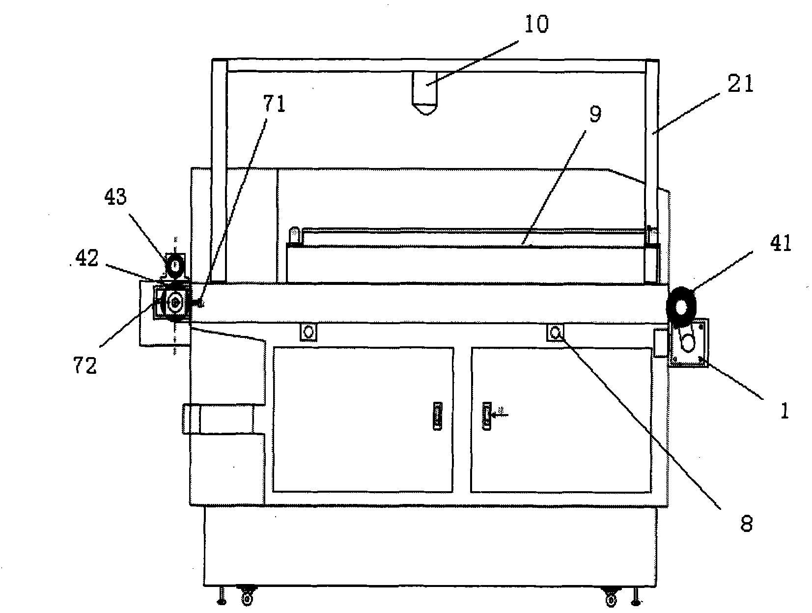
[0016] A kind of panorama laser cutting bed of the present invention, see image 3 with Figure 4 , the panoramic laser cutting machine includes a motor 1, a frame 2, a discharge rubber roller 41, a feed rubber roller 42, a mesh belt 6 and a tension adjustment device 7, and the motor 1 passes through the gear of the belt 3 and the discharge rubber roller 41. Connection; the mesh belt 6 is set on the frame 2 through the mesh belt bracket 8 and can move along the guide rail 9; the guide rail 9 is set on the frame 2; the motor 1 is set on the outer front of the frame 2, and the discharge rubber roller 41 is located The outer front part of the frame 2 and one end of the discharge rubber roller 41 are connected with the motor 1, and the other end is arranged on the frame 2 through the fixed frame 20; the feeding rubber roller 42 is positioned at the rear of the frame 2, and the feeding rubber One end of the roller 42 is arranged on the frame 2 through the rubber roller bracket 21 ...


PUM


Abstract

The invention discloses a full-view laser cutting bed. An electrical machine is connected with a gear of a discharging rubber roller through a belt; a mesh belt is arranged on a frame through a mesh belt bracket and can slide along a guide rail; the guide rail is arranged on the frame; the electrical machine and the discharging rubber roller are arranged at the front part outside the frame, one end of the discharging rubber roller is connected with the electrical machine and the other end is arranged on the frame through a fixed mount; a feeding rubber roller is arranged at the rear part of the frame, one end of the feeding rubber roller is arranged on the frame through a rubber roller bracket and the other end is arranged on the frame through a tension adjustment device; and a material pressing roller is arranged above the feeding rubber roller, the frame is provided with a camera for shooting images to be cut on the mesh belt, and the camera is connected with a control device. The cutting bed can cut according to shaped pattern surfaces and materials, and can be widely applied to textiles, clothing, printing, trademarks, advertising and other industries.

Description

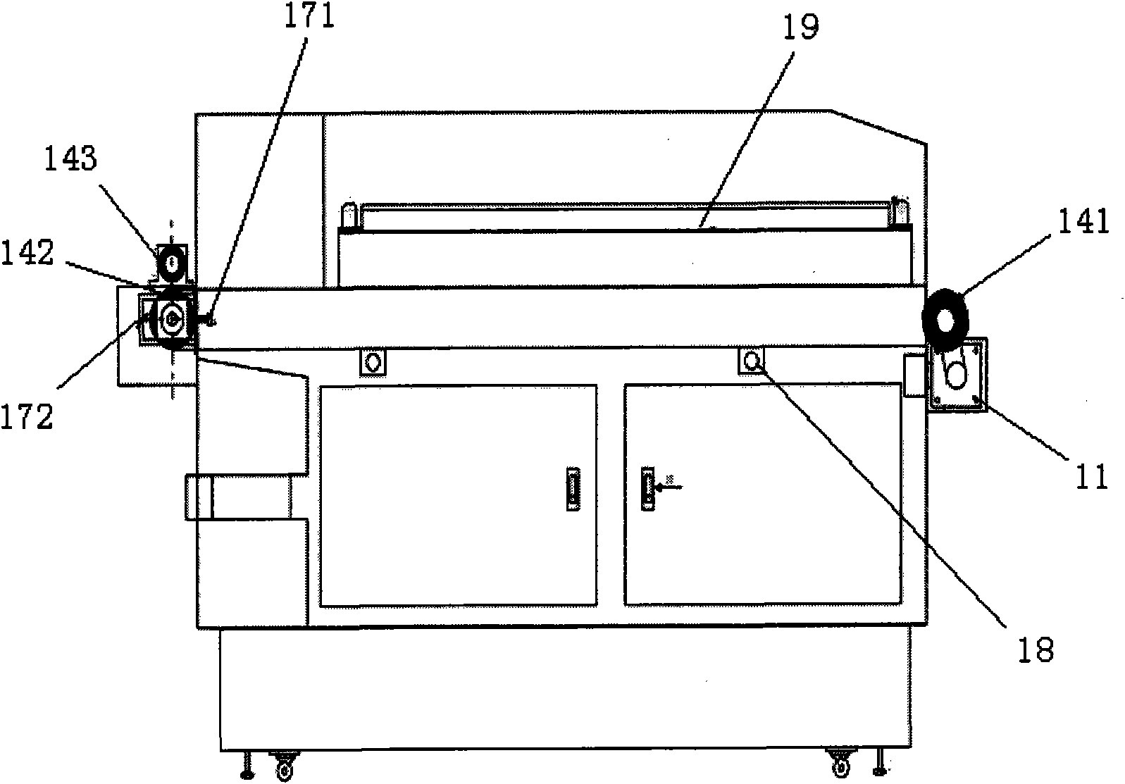
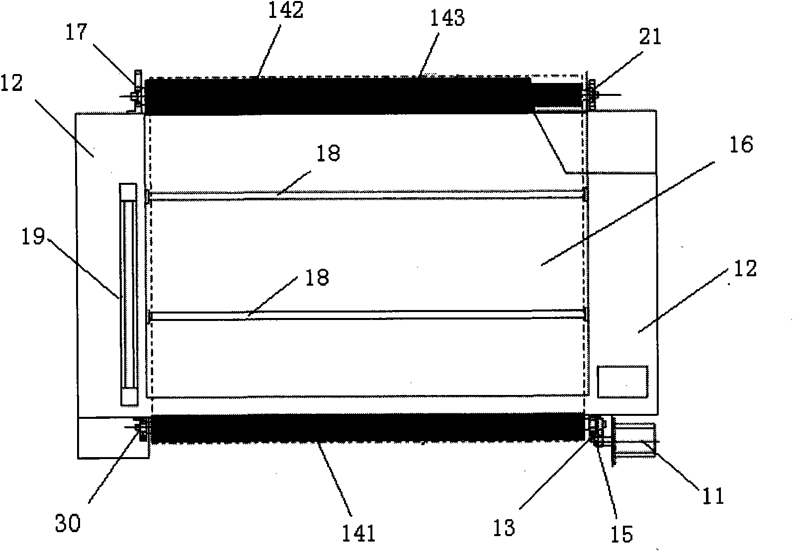
technical field [0001] The invention relates to a laser cutting machine, in particular to a panoramic laser cutting machine for engraving or cutting rubber, plastic, textiles and other non-metallic materials according to a set pattern. Background technique [0002] With the improvement of computer automatic control technology, laser engraving and cutting machines have been widely used. Using laser engraving and cutting, the process is very simple, just like using a computer and printer to print on paper, it can precisely engrave and cut non-metallic materials or metal materials such as rubber, plastic, and textiles. The structure of the existing laser engraving and cutting machine for cutting woven fabrics is shown in figure 1 with figure 2 , comprising a motor 11, a frame 12, a belt 13, a discharge rubber roller 141, a feed rubber roller 142, a gear 15, a mesh belt 16 and a tension adjustment device 17. The motor 11 is connected with the gear 15 of the discharge rubber ...

Claims


Application Information

Patent Timeline
Patent Type & Authority Applications(China)
IPC IPC(8): B23K26/36B23K26/42B23K26/38B23K26/70
Inventor 彭绍益
Owner 江苏大华激光科技开发有限公司
Learn More