
Device for flexibly shifting cylindrical grinding machine workpiece

A technology for cylindrical grinding machines and workpieces, which is applied in the direction of grinding machines, machine tools designed for grinding the rotating surface of workpieces, manufacturing tools, etc., which can solve the problems of easily damaged center hole quality, torque asymmetry, and poor product accuracy, and achieve improvement. Grinding quality, ensuring balanced force, and improving the effect of rotation accuracy

Inactive Publication Date: 2010-12-15
SINOSTEEL XINGTAI MACHINERY & MILL ROLL
View PDF5 Cites 6 Cited by
  • Summary
  • Abstract
  • Description
  • Claims
  • Application Information

AI Technical Summary

Problems solved by technology

Using a single lever to toggle, the point of action of the force is on the outer circle of the workpiece. The force on the workpiece is relatively biased, and the rotation accuracy of the workpiece is also poor. It is not easy to process high-precision products, and it is easy to grind the center hole.
Due to structural reasons, it is difficult to make the force of the two levers equal, and it is even more difficult to ensure that the two forces are equidistant from the center of the workpiece. Therefore, there is also the phenomenon of torque asymmetry, and the processed Product accuracy is also poor
[0003] In addition, the hard-connected shifting method is adopted, especially for large and heavy shaft workpieces, the impact force on the workpiece is relatively large when starting, and the quality of the center hole is easily damaged, resulting in the appearance of grinding vibration marks. It is also difficult to fundamentally improve the rotating quality of the workpiece

Method used


Image

  • Device for flexibly shifting cylindrical grinding machine workpiece
  • Device for flexibly shifting cylindrical grinding machine workpiece
  • Device for flexibly shifting cylindrical grinding machine workpiece

Examples


Embodiment 1

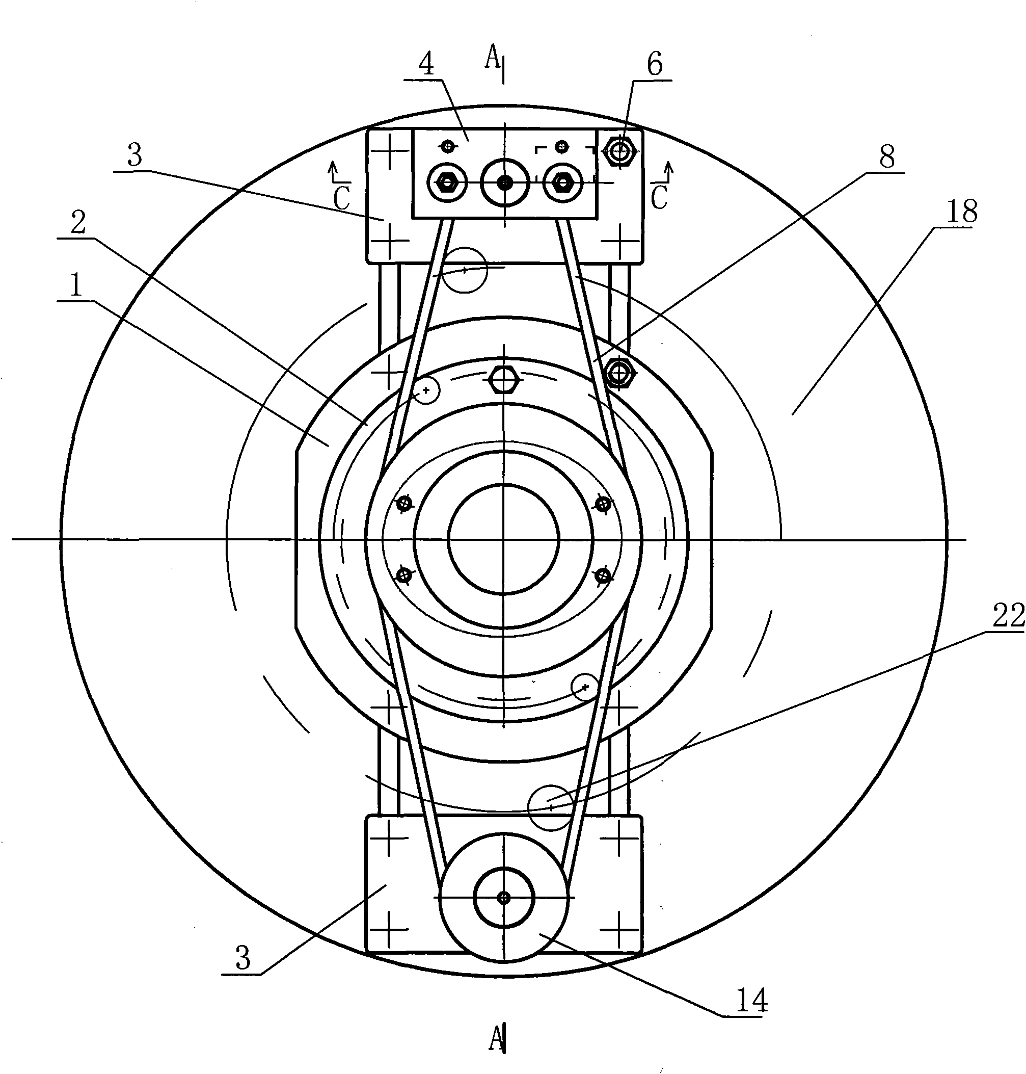
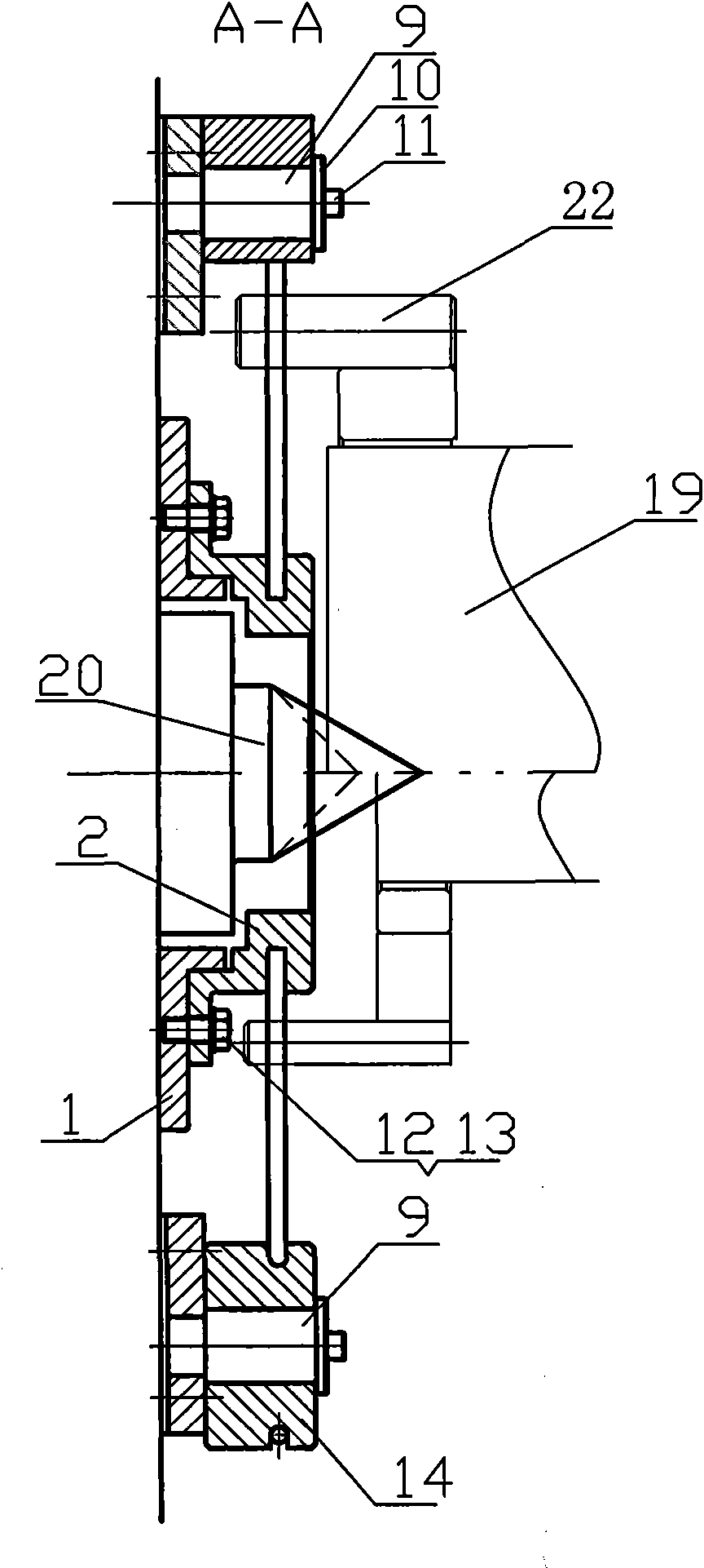
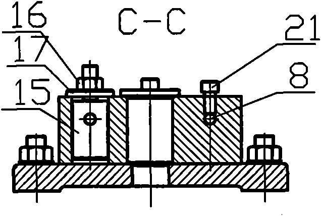
[0023] Such as figure 1 and figure 2 The workpiece soft dialing device of the cylindrical grinding machine shown is to install a turntable 2, a turnwheel 14 and a turntable 4 on the turntable 18 of the main shaft of the grinding machine. The wheel 14 and the turning block 4 are located on both sides of the turntable 2 respectively, and a steel wire rope 8 is wound between the turn block 4 , the turning wheel 14 and the turntable 2 . The turntable 2 is fixed on the grinder spindle turntable 18 through the base 1, the turn block 4 and the turn wheel 14 are respectively fixed on the two ends of the T-shaped groove of the grinder turntable 18 through a small base 3, the turn block 4 and the turn wheel 14 respectively pass through the rotating shaft 9 is assembled on the small base 3, and the gland 10 is pressed on the top of the rotating shaft 9 with the hexagon socket head cap screw 11, and the rotating block 4 and the rotating wheel 14 can rotate around the rotating shaft 9; ...

Embodiment 2

[0029] Figure 4 It is another structure of the workpiece soft dialing device for the cylindrical grinder, which is different from Embodiment 1 in that the ring groove for tensioning the steel wire rope set on the turntable 2 is a stepped ring groove. When installing the wire rope, first rotate the step-shaped ring groove so that the step line of the steps at both ends of the step-shaped ring groove is parallel to the center connection line between the turning block and the runner, then wind the wire rope in the step groove, and wrap the two ends of the wire rope After the head is fixed by the method in Example 1, rotate the turntable so that the step line of the step-shaped ring groove is perpendicular to the center connection line between the turning block and the runner, so that the wire rope ring is tensioned. The step-shaped ring groove is easy to process and convenient to manufacture, and the cost is lower than that of the elliptical ring groove.

Embodiment 3

[0031]Embodiment 1 and Embodiment 2 are generally used for large-scale cylindrical grinders to process and grind large-scale high-precision rolls and shaft parts. For small and medium-sized cylindrical grinders, the base 1 and the turntable 2 can be removed, and the T-bolt 6 can be loosened. Nut, widen the distance between the two small bases 3, after the wire rope ring is properly tensioned, the T-bolt 6 is tightened to position the two small bases 3. Because the diameter of the runner 14 and the distance between the two rotating shafts 9 are relatively large, the wire rope ring and the top 20 will not interfere during work. In this way, the structure of the soft dialing device is simplified, and the processing accuracy of the small cylindrical grinding machine can be effectively improved.


PUM


Abstract

The invention discloses a device for flexibly shifting a cylindrical grinding machine workpiece, which comprises a rotating disk, a rotating wheel and a rotating block which are connected on the rotating disk of the main shaft of the grinding machine, wherein the rotating wheel and the rotating block are respectively positioned at two sides of the rotating disk, and a wire rope is wound among the rotating block, the rotating wheel and the rotating disk. After a workpiece is tightly clamped by a workpiece clamping ring, two shifting rods of the workpiece clamping ring are put in a wire rope ring, and the wire rope drives the ground workpiece to rotate through the two shifting rods. The device of the invention is matched with a cylindrical grinding machine to be used for grinding shaft cylinders, and the device can be used for shifting the ground workpiece to rotate, thereby effectively improving the rotating accuracy and the grinding quality of the ground workpiece.

Description

technical field [0001] The invention relates to a process device matched with a machine tool, in particular to a soft dialing device for workpieces of an outer cylindrical grinder. Background technique [0002] In the field of mechanical processing, during the process of grinding the outer circle of the workpiece by using the cylindrical grinder, the workpiece is fixed on the grinder by the two tops at both ends of the cylindrical grinder, and the end of the workpiece close to the spindle turntable of the grinder is fitted with a belt The snap ring of the driving rod, the driving rod is in contact with the turntable of the main shaft of the grinding machine. During grinding, the rotation of the workpiece is to drive the rotation of the workpiece by turning the lever on the turntable. There are two forms of single lever or double lever, but they all adopt hard connection. Using a single-lever toggle, the point of force is on the outer circle of the workpiece. The force on t...

Claims


Application Information

Patent Timeline
Patent Type & Authority Applications(China)
IPC IPC(8): B24B5/35
Inventor 郭学信刘宏伟李立新
Owner SINOSTEEL XINGTAI MACHINERY & MILL ROLL
Learn More