
Wind speed and direction testing device based on light spot position sensitivity

A technology of wind speed, wind direction, and testing equipment, which is applied in measuring equipment, fluid velocity measurement, velocity/acceleration/shock measurement, etc., and can solve measurement range, power consumption and temperature drift limitations, frequent maintenance of moving parts, large size of mechanical devices, etc. problem, to achieve the effect of low power consumption, easy installation or portability, and small size

Inactive Publication Date: 2010-12-15
SOUTHEAST UNIV
View PDF3 Cites 11 Cited by
  • Summary
  • Abstract
  • Description
  • Claims
  • Application Information

AI Technical Summary

Problems solved by technology

These mechanisms are large, expensive, and have moving parts that require frequent maintenance
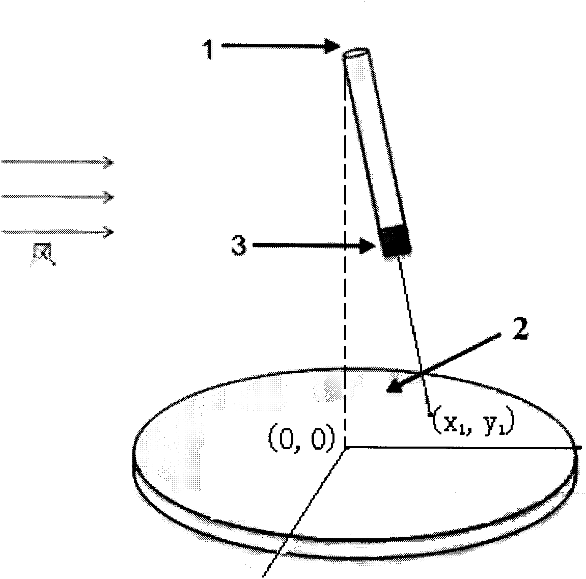
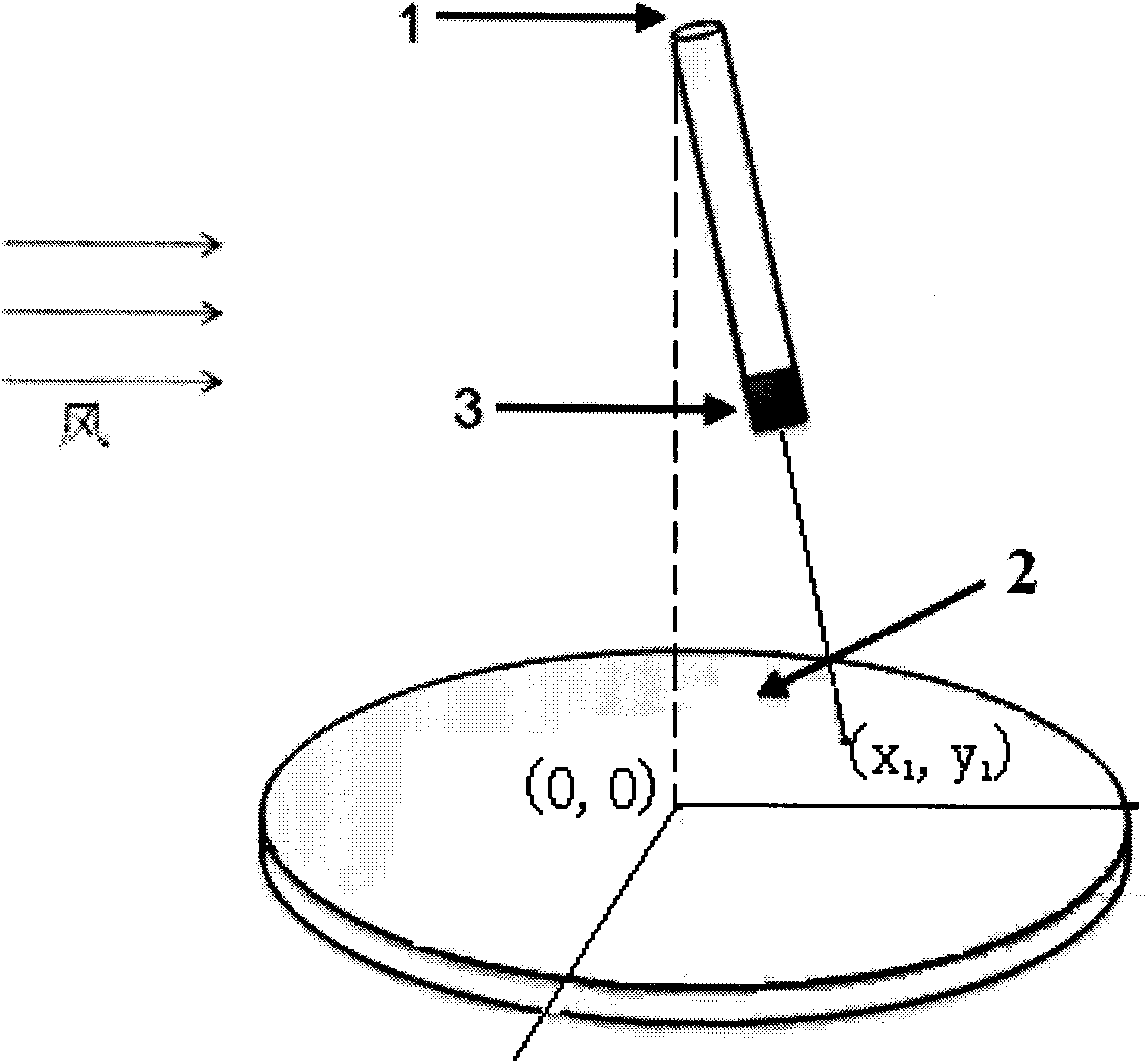
[0004] In recent years, sensors have developed towards miniaturization, and wind speed and direction sensors based on thermal principles have been greatly developed. At the same time, there are limitations in measurement range, power consumption, and temperature drift.

Method used


Image

  • Wind speed and direction testing device based on light spot position sensitivity
  • Wind speed and direction testing device based on light spot position sensitivity

Examples


Embodiment Construction

[0013] The following is a detailed description of the embodiments of the present invention. This embodiment is implemented on the premise of the technical solution of the present invention, and detailed implementation methods and specific operating procedures are provided, but the protection scope of the present invention is not limited to the following implementation example.

[0014] As shown in the drawings, this embodiment includes a wind sensitive rod 1, a light point position detection sensor 2 and a light emitter 3, wherein: the wind sensitive rod 1 is a vertical cantilever structure, and the light emitter 3 is located on the suspended part of the wind sensitive rod 1 At the end, the light spot position detection sensor 2 is horizontally arranged under the wind sensitive rod 1 .

[0015] The wind-sensitive rod 1 is a hollow structure made of elastic material, and a wire for connecting the light emitter 3 is provided at the hollow position.

[0016] The projection of th...


PUM


Abstract

The invention discloses a wind speed and direction testing device based on light spot position sensitivity, comprising a wind-sensitive rod, a light spot position detection sensor and a light emitter, wherein the wind-sensitive rod is of vertical cantilever structure; the light emitter is arranged at the suspended terminal of the wind-sensitive rod; and the light spot position detection sensor is horizontally arranged below the wind-sensitive rod. Compared with the traditional testing devices, the testing device of the invention has the advantages of small volume, adjustable range, convenient installation or carrying, low power consumption, small temperature drift, convenient maintenance, etc.

Description

technical field [0001] The invention relates to a sensing test device for measuring wind speed and direction, in particular to a wind speed and direction test device based on light spot position sensitivity. Background technique [0002] At present, most of the weather stations in China are manually observed weather stations, and the measured data are read from the instruments manually. This makes the measurement of meteorological data requires a lot of manual labor. And measuring instruments cannot be installed in many places, so that the automatic detection of meteorological conditions cannot be completed. With the popularity of computers, weather detection can be fully automated, and then automatic weather stations appear. An automatic weather station is a weather station that automatically performs meteorological observation, data collection, and transmission under the control of electronic equipment or computers. The emergence of automatic weather stations saves a lo...

Claims


Application Information

Patent Timeline
Patent Type & Authority Applications(China)
IPC IPC(8): G01P5/02G01P13/02
Inventor 秦明季晶
Owner SOUTHEAST UNIV
Learn More