
Intelligent protective loop framework system and intelligent protecting method of power supply looped network

A technology of intelligent protection and power supply ring, applied in emergency protection circuit devices, electrical components, etc., can solve the problems of increasing project cost, low failure rate of 35kV ring network feeder, and expensive differential protection device, and achieves the protection time limit. Effect

Active Publication Date: 2010-12-15
CHINA RAILWAY ELECTRIFICATION SURVEY DESIGN & RES INST +1
View PDF4 Cites 18 Cited by
  • Summary
  • Abstract
  • Description
  • Claims
  • Application Information

AI Technical Summary

Problems solved by technology

Since the price of the differential protection device is relatively expensive, and the failure rate of the 35kV ring network feeder is relatively small, this configuration will inevitably increase the cost of the project
[0004] To sum up, these contradictions cannot be resolved ideally by using the traditional idea of ​​protection cooperation

Method used


Image

  • Intelligent protective loop framework system and intelligent protecting method of power supply looped network
  • Intelligent protective loop framework system and intelligent protecting method of power supply looped network
  • Intelligent protective loop framework system and intelligent protecting method of power supply looped network

Examples


Embodiment 1

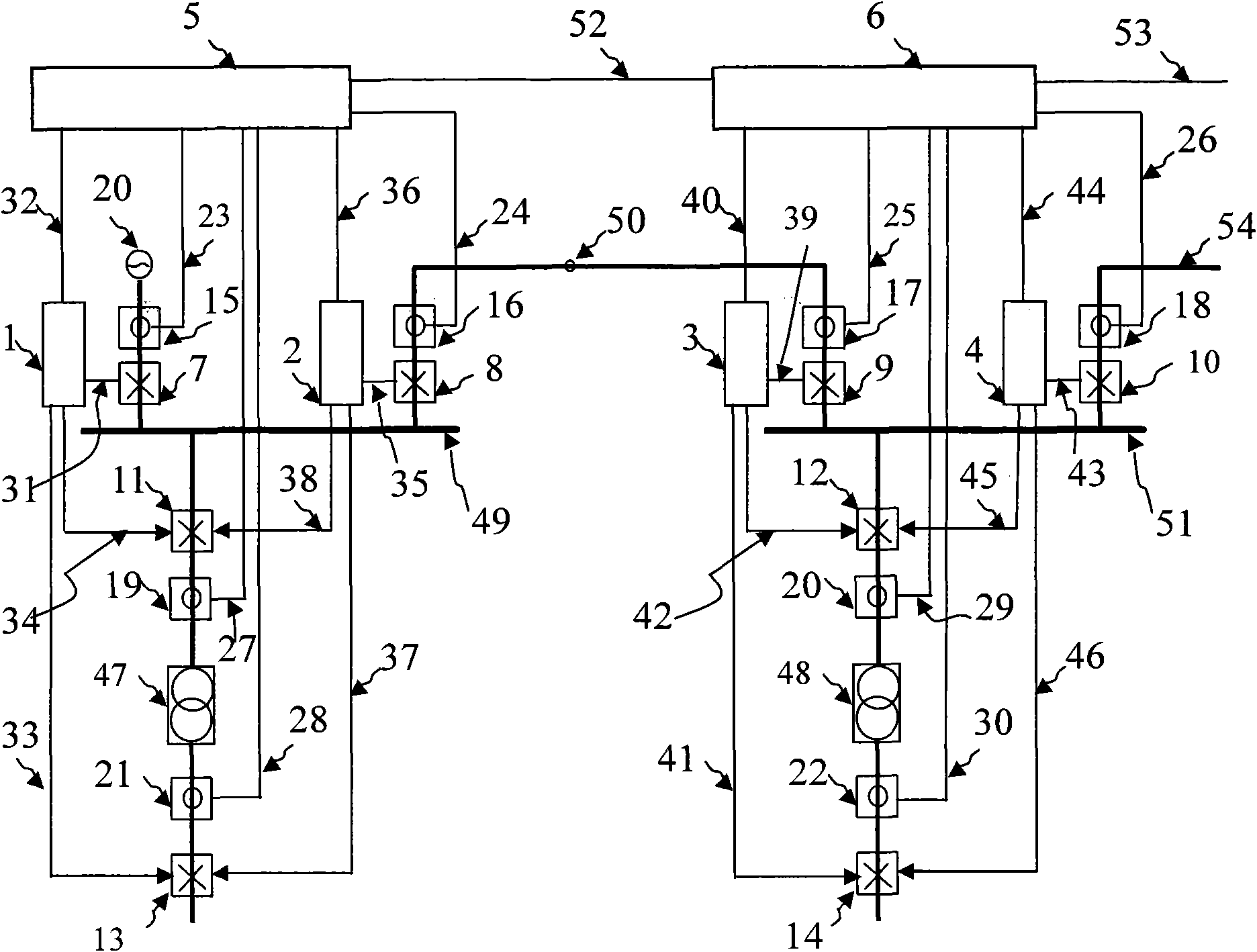
[0068] Embodiment 1, the intelligent protection circuit architecture system of the power supply ring network, such as figure 1 Shown include:

[0069] first substation

[0070] Incoming line branch: composed of the first circuit breaker 7 and the first current sensor 15 connected in series, used to receive the power supply from the external power supply 20 and feed power to the first section of the bus 49;

[0071] The first bus bar 49: on the one hand, it transmits power to the first feeder, and on the other hand, it transmits power to the next remote circuit (ie, the second substation) through the first ring network cable 50;

[0072] The first ring network power transmission branch: composed of the second circuit breaker 8 and the second current sensor 16 connected in series, and connected in series between the first section of the bus 49 and the first ring network cable 50;

[0073] The feeder loop on the first section bus 49: there is at least one feeder loop on the fir...

Embodiment 2

[0102] Embodiment 2, the intelligent protection method of the power supply ring network, including:

[0103] 1. Determining the protection domain: take each segment of the busbar in the power supply ring network, each ring network cable, and the transformer in each feeder circuit as an independent protection object, and the incoming line circuit breaker and outgoing line circuit breaker directly connected to each protection object. The protection domain that constitutes the protection object;

[0104] 2. Determine the backup protection domain: the nearest circuit breaker immediately behind any circuit breaker in each protection domain and other circuit breakers constitute the backup protection domain of the protection domain, and each protection domain has more than one backup protection domain ;

[0105] 3. Judgment of whether each protection domain starts to work: each protection device determines whether each protection domain starts to work according to the detected curre...

Embodiment 3

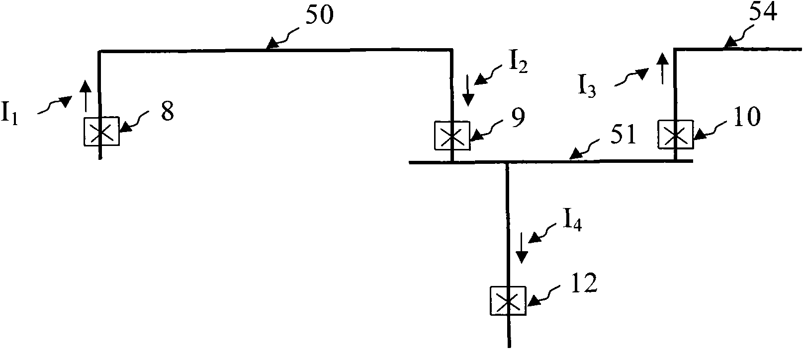
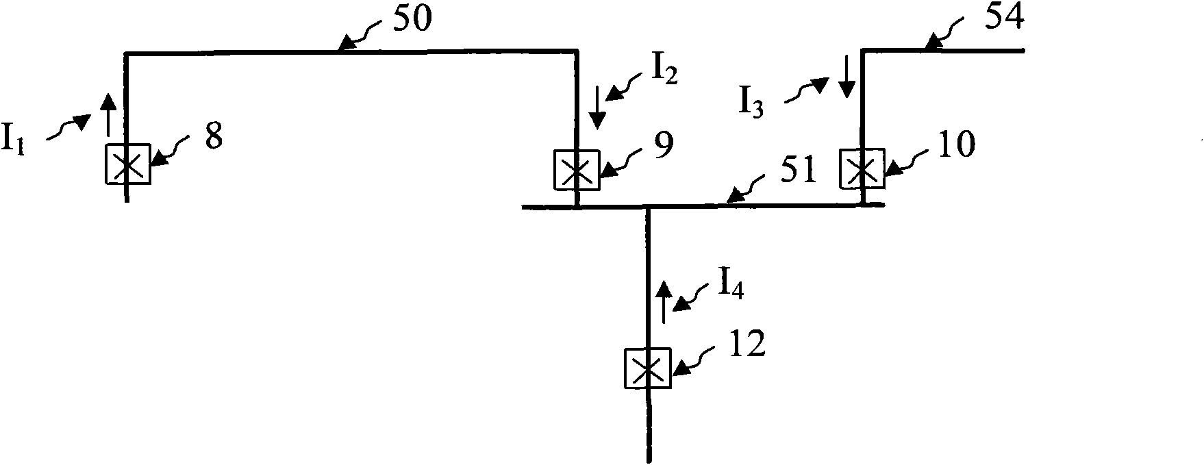
[0118] Such as figure 2 as shown, figure 2It expresses the current distribution in the current sensor in the relevant loop when the ring network has a normal load current. In order to express clearly, the graphic symbols of the current sensor at each point are hidden. The protection method of the system of the present invention:

[0119] figure 2 in the I 1 The arrow direction of the current (pointing to the ring network cable 50) is defined as positive, I 2 Current direction and I 1 The current direction is the same, therefore, the current I on both sides of the ring network cable 50 1 and I 2 The currents are equal in magnitude and in the same direction:

[0120] I 1 +I 2 ≥kI 1 , where k takes a value of 1.2 to 1.7, indicating that the short-circuit point is not between the circuit breaker 8 and the circuit breaker 9, which meets the non-action criterion, so neither the second circuit breaker 8 nor the third circuit breaker 9 trips.

[0121] For the protection ...


PUM


Abstract

The invention relates to an intelligent protective loop framework system and an intelligent protecting method of a power supply looped network. The system uses transformers in various sections of buses, various looped network cables and various feed line loops in the power supply looped network as independent protective objects, all protective objects form a protective region of the protective objects through wire inlet and outlet breakers directly connected with the protective objects; information resource sharing is achieved through networking related current sensors with related protectivedevices, the protective devices can extract output information of any one sensor on the network, if the protective objects have short circuit faults, and all various related protective devices can rapidly extract current information at two ends of a fault region for comprehensive judgment so as to rapidly cut off the circuit breakers at two ends of the fault region by using short delay; and if the circuit breaker of the fault region rejects the separating brake because of the fault, the system enlarges the protection to a standby region. The system is suitable for massive popularization and application because the protection does not need setting calculation, and has important production practical significance.

Description

【Technical field】 [0001] The invention relates to the technical field of relay protection for 35kV, 10kV, 0.4kV medium and low voltage ring network power supply systems of urban rail transit power supply systems, in particular to an intelligent protection loop architecture system and an intelligent protection method for a power supply ring network. 【Background technique】 [0002] The power supply system of rail transit consists of the main substation or switch substation that provides power and the traction or step-down substation distributed in each station. The main substation or switch station transmits 35kV or 10kV power to each station through cables. The incoming line circuit breaker of the station substation is connected to the outgoing line circuit breaker through the 35kV or 10kV busbar of the substation, and then output to the incoming line of the next station substation through the outgoing line circuit breaker, and so on, forming Power supply ring network. [00...

Claims


Application Information

Patent Timeline
Patent Type & Authority Applications(China)
IPC IPC(8): H02H7/26
Inventor 王术合姜春林赵印军韩鲁斌张云太李继胜孟祥奎杨啸勇余满峰王立天田胜利
Owner CHINA RAILWAY ELECTRIFICATION SURVEY DESIGN & RES INST
Learn More