
Manufacturing of low-friction elements

A low-friction, mechanical component technology, applied in the direction of engine components, pressure inorganic powder coating, coating, etc., can solve the problem of high production cost

Active Publication Date: 2010-12-15
APPLIED NANO SURFACES SWEDEN AB
View PDF3 Cites 4 Cited by
  • Summary
  • Abstract
  • Description
  • Claims
  • Application Information

AI Technical Summary

Problems solved by technology

An entire new manufacturing process step and manufacturing tooling had to be provided, which made production very expensive
[0008] Furthermore, the solid lubricant layers provided by prior art methods have inherent defects of different kinds

Method used


Image

  • Manufacturing of low-friction elements
  • Manufacturing of low-friction elements
  • Manufacturing of low-friction elements

Examples


Embodiment Construction

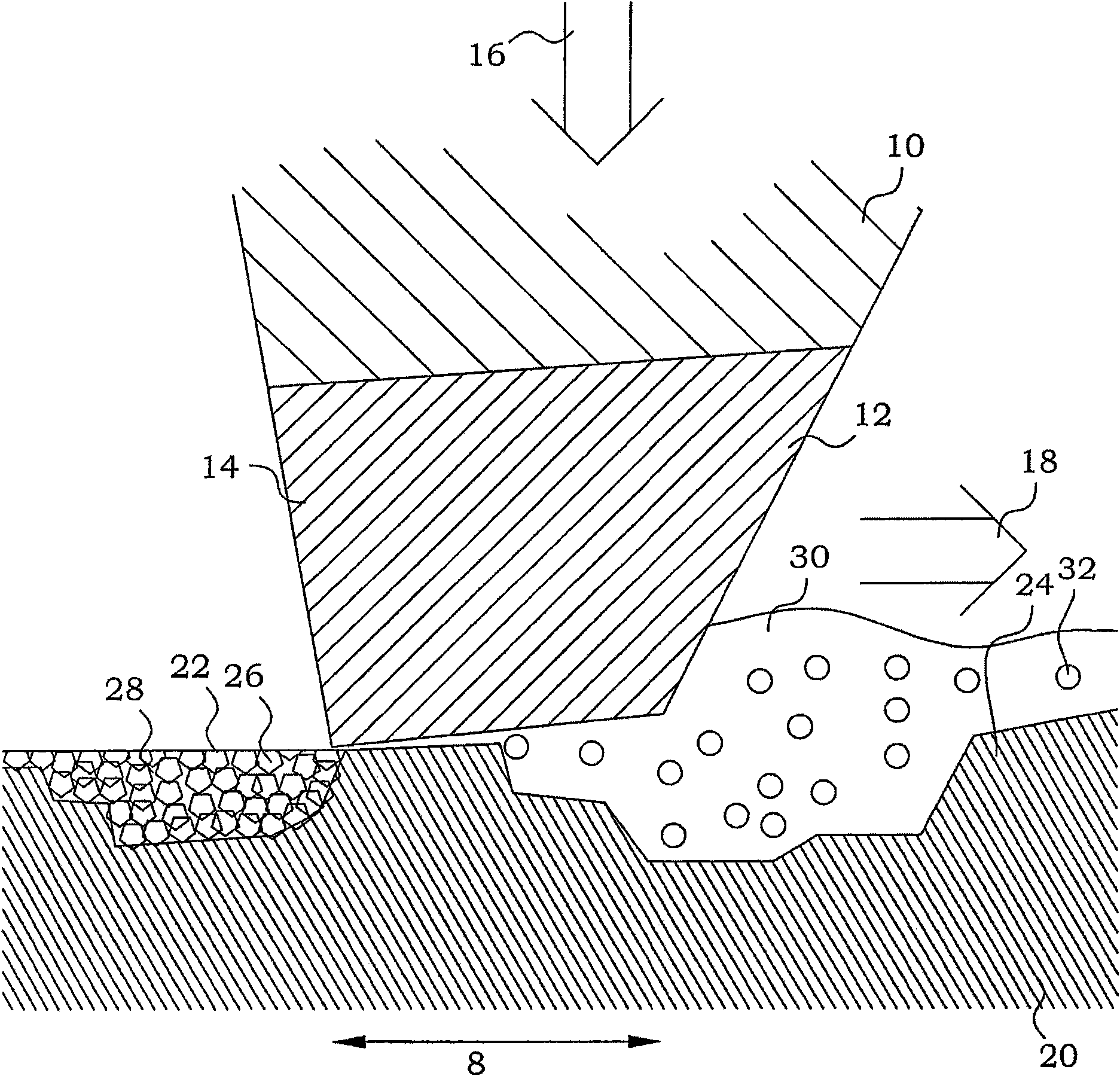
[0026] In this description, identical or directly related features in different figures and embodiments are denoted by the same reference numerals.

[0027] In this specification, the term "transverse" is used. In this specification, the intended meaning of motion in two intersecting directions on or along a surface is defined by two non-parallel motions intersecting a point on the surface. Figure 10A Two examples of motion considered non-intersecting are shown. Figure 10B Three non-exclusive examples of cross motion are shown. In these examples, there is at least one point on the aforementioned surface passing through two non-parallel directions.

[0028] According to the invention, a surface with a solid lubricant is provided by direct tribochemical deposition onto the surface to be covered, preferably a relatively rough surface. Tribochemical deposition is well known in the field of friction and wear. For example, in a 2006 review of the doctoral dissertation "On the ...


PUM


Abstract

A manufacturing method of mechanical elements comprises providing (210) of a mechanical element having a rough curved surface preferably with a surface roughness of more than Sa = 0.1 mum. The method is characterized by tribochemically depositing (214) solid lubricant substance directly onto the rough curved surface in transverse directions. A mechanical element has a curved surface. The curved surface has a surface layer of a tribochemically deposited solid lubricant substance. The mechanical element is obtainable by the above method. A tool for manufacturing of such a mechanical element comprises a support portion, at least one tool working surface, means for providing a force pressing the tool towards the curved surface and driving means for moving said at least one tool working surface in two different directions along said curved surface. The working surface comprises an oxide, carbide and / or suicide of an element capable of forming a stable sulfide.

Description

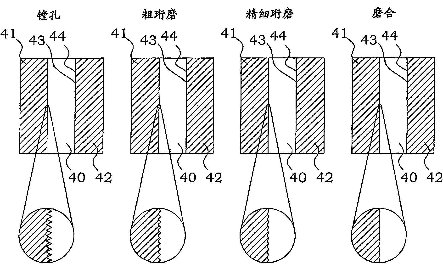
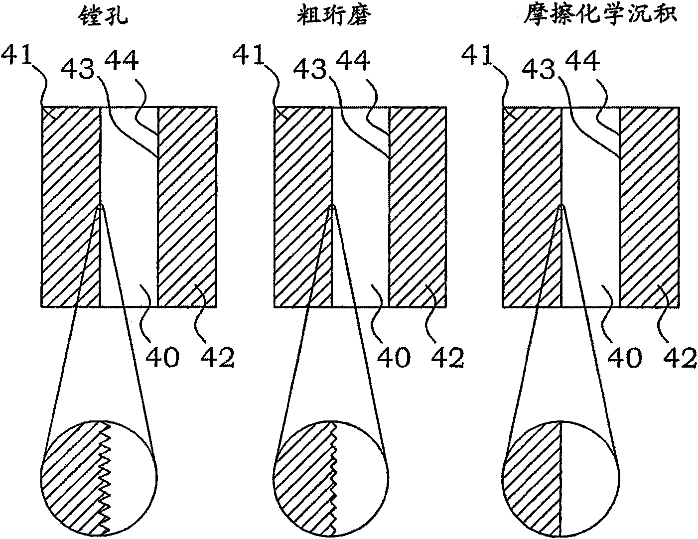
technical field [0001] The present invention generally relates to the manufacture of low friction elements, associated tooling and elements manufactured therefrom. Background technique [0002] In internal combustion engines, the combustion process is often allowed to occur within the cylinder, thereby forcing the piston to move relative to the cylinder. This relative movement must be low-friction so as not to waste the energy released by the combustion process, in particular not to convert the released energy into heat in the piston and cylinder. Furthermore, the physical relationship between the piston and cylinder must be such that any leakage of combustion gases is minimized. [0003] For this purpose, the inner surface of the cylinder is carefully processed to achieve a final surface roughness typically in the range Sa = 0.15-0.50 μm. This surface treatment process can usually be carried out in a number of steps: boring, rough honing, fine honing, top honing and possi...

Claims


Application Information

Patent Timeline
IPC IPC(8): C23C26/00C23C24/02C23C24/06B24B1/00B24B33/08F02F1/20
CPCC23C24/02C23C24/06B24B1/00C23C26/00B24B33/08Y10T428/13Y10T428/31504
Inventor 尼尔斯·斯塔夫利德
Owner APPLIED NANO SURFACES SWEDEN AB
Learn More