
High treatment capacity feed atomizing nozzle

A technology of atomizing nozzles and processing capacity, which is applied in the direction of chemical/physical/physical-chemical nozzle reactors, injection devices, liquid injection devices, etc., which can solve the difficulties in the layout of process pipelines and on-site operations, and the inability to arrange all nozzles in risers, The strength of the riser is difficult to produce safely, and the effects of high anti-wear performance, low dry gas production rate and moderate injection speed are achieved.

Active Publication Date: 2010-12-22
CHINA PETROCHEMICAL CORP +3
View PDF0 Cites 13 Cited by
  • Summary
  • Abstract
  • Description
  • Claims
  • Application Information

AI Technical Summary

Problems solved by technology

For some nozzles currently used in domestic FCC devices, such as KH, BWJ, CS nozzles, etc., the processing capacity of a single nozzle is mostly below 40t / h. When it exceeds 45t / h, the following problems appear: (1) The atomization particle size changes (2) The flow distribution and particle size distribution after atomization are poor
When the processing capacity of the device is further increased, because the diameter of the riser of the device is limited by the process requirements, if the number of nozzles is increased to meet the requirements of the processing capacity, it will cause that all nozzles cannot be arranged on the riser; or because the opening holes on the riser are too large Intensive, so that the strength of the riser is difficult to meet the requirements of safe production
In addition, too many nozzles will increase the number of process pipelines and valves, which will bring many difficulties to the layout of process pipelines and on-site operations.

Method used


Image

  • High treatment capacity feed atomizing nozzle
  • High treatment capacity feed atomizing nozzle
  • High treatment capacity feed atomizing nozzle

Examples


Embodiment Construction

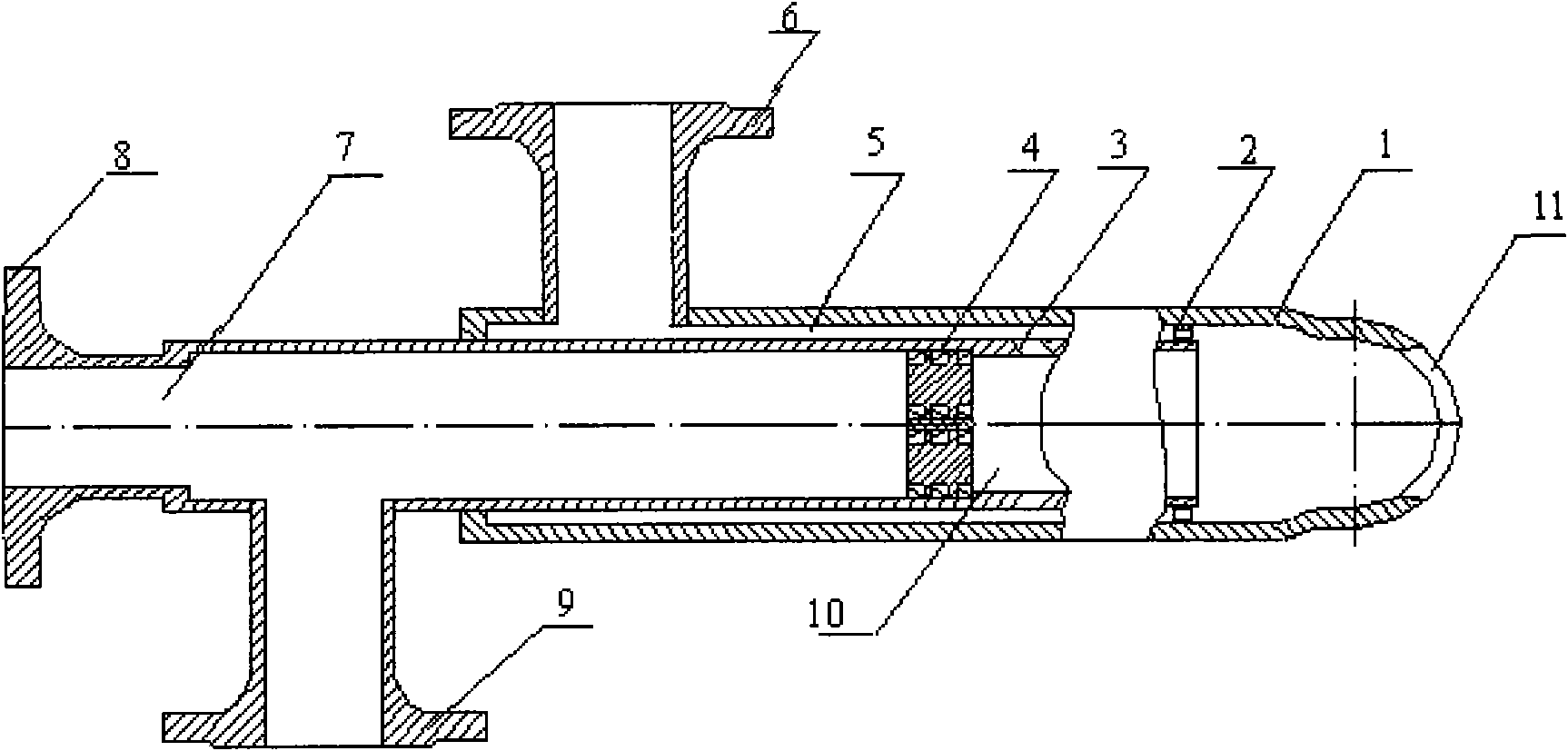
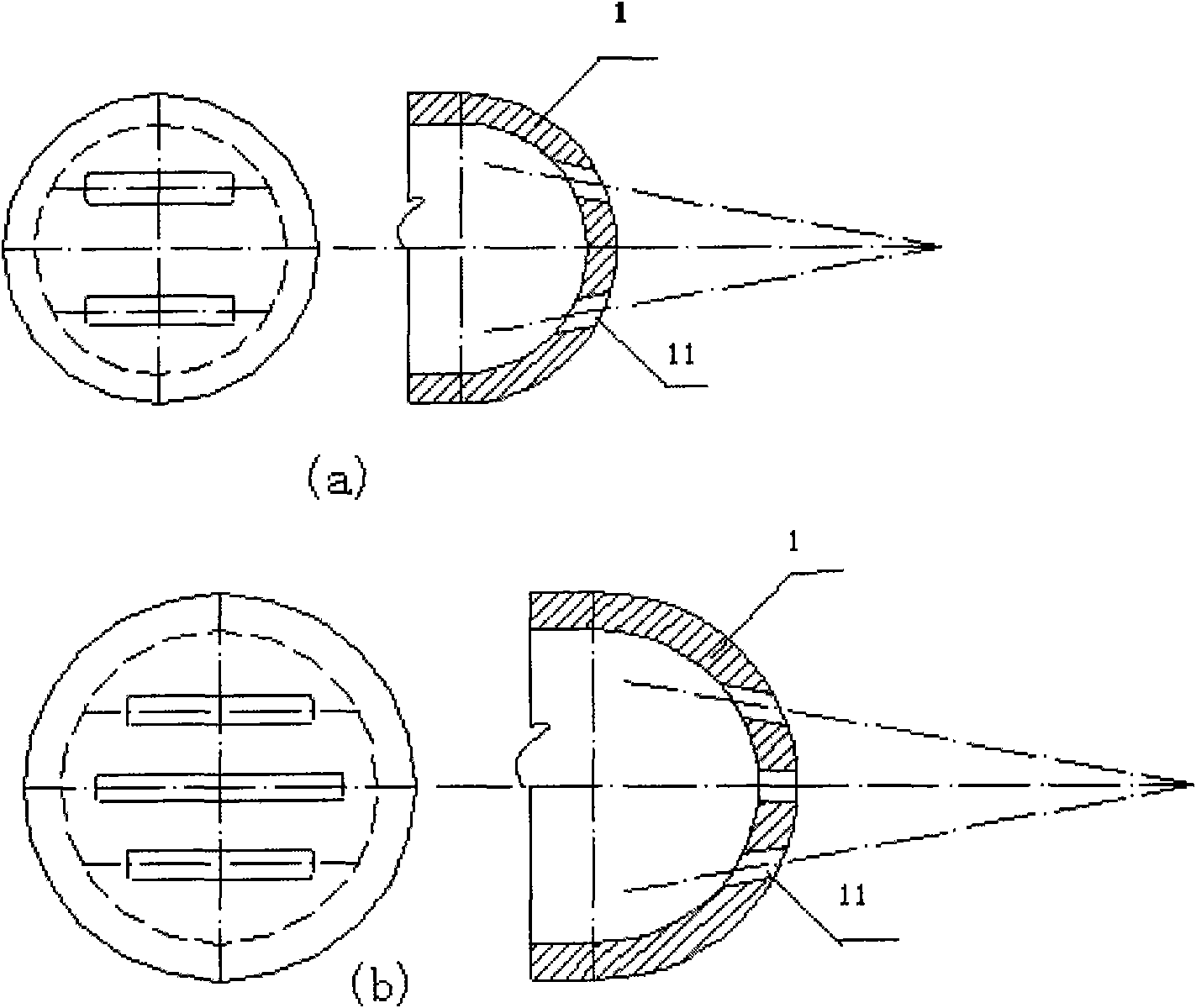
[0034] Such as figure 1 As shown, a large-capacity feed atomization nozzle includes a primary air intake pipe and a secondary air intake pipe, and the central axis of the two is on the same line as the central axis of the nozzle; the secondary air intake pipe is sleeved on the primary The outer side of the air intake pipe, the jacket space therebetween forms a secondary air intake chamber 5; the primary air intake pipe includes an air inlet 8, an oil inlet 9, a mixing chamber 7 and an injection pipe 10; the secondary air intake pipe includes Secondary air inlet 6, nozzle 1 and nozzle hole 11.

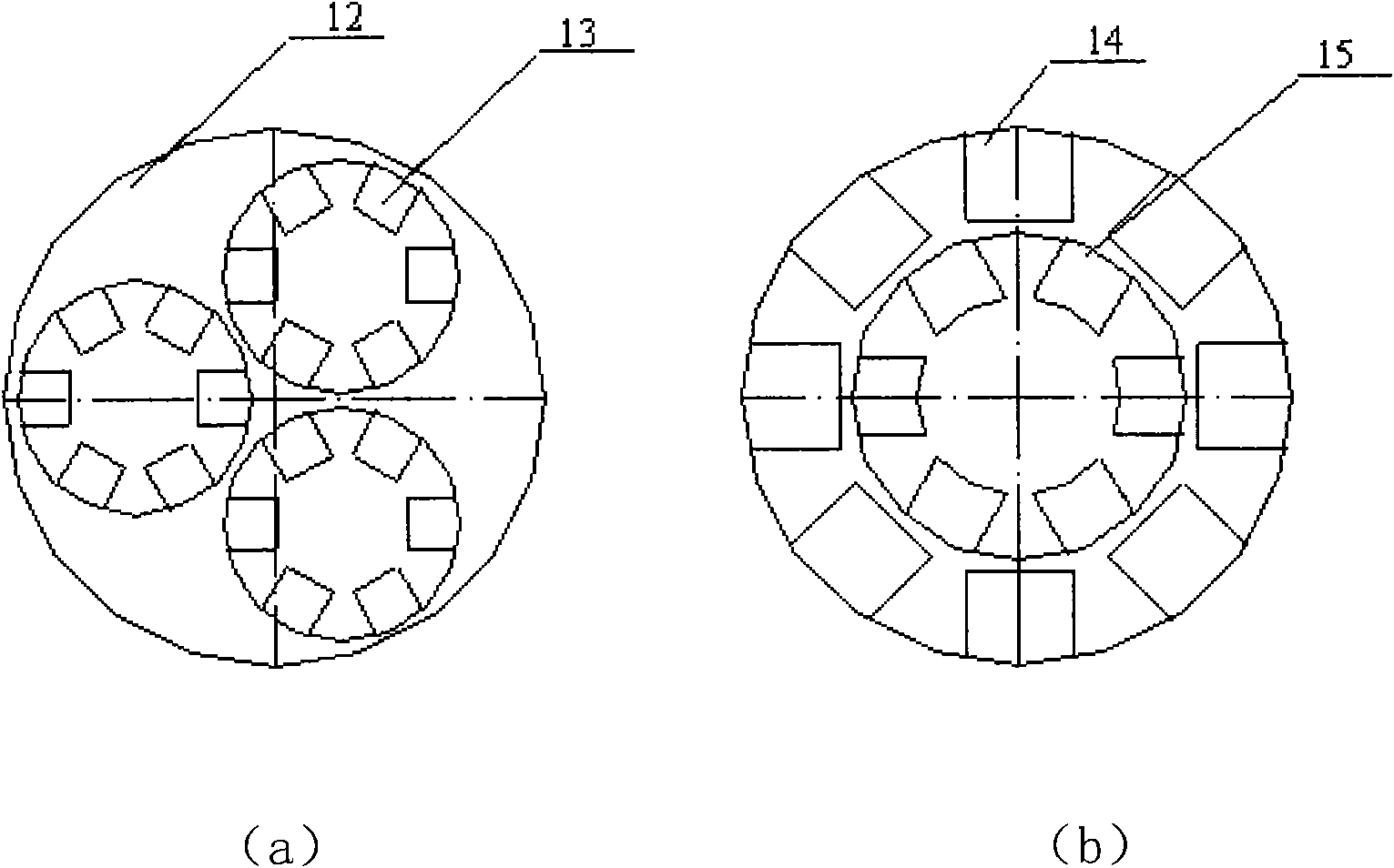
[0035] A combined swirler 4 is installed between the mixing chamber 7 and the injection pipe 10 in the primary air intake pipe, and the combined swirler includes a group of small-diameter swirlers.

[0036] The nozzle adopts a multi-point gas injection structure, that is, a group of secondary air holes 3 are opened on the wall of the injection pipe 10 in the primary air intake pipe, an...


PUM


Abstract

The invention provides a high treatment capacity feed atomizing nozzle, and belongs to the field of petrochemical equipment. A combined cyclone, a multi-point gas injection structure and a spray-head with a porous impinging structure are adopted; and a hard alloy surfacing structure is adopted at orifices. The nozzle is suitable for feed atomizing nozzles of heavy oil FCC devices with the yield of 3,500,000-6,000,000 tons / year, the treatment capacity of a single nozzle is 60-100t / h, and a defect that the dimension of the nozzle is changed due to high treatment capacity so as to cause low atomizing effect is improved; meanwhile, the nozzle has the atomized particle size in a range of 60+ / -10 mu m, the liquid layer on the injected sector surface is distributed uniformly, the yield of light oil is high, the productivity of dry gas is low, and the coking in the tubes is improved; besides, the steam consumption is low, and the gas / liquid ratio is between 3 and 6 percent (raw materials). In addition, the injecting speed of the nozzle is medium, a phenomenon that a catalyst is broken cannot occur in the production, and the nozzle has high wear resistance and the service life of more than 5 years.

Description

technical field [0001] The invention belongs to the field of petrochemical equipment, and in particular relates to a large-capacity feed steam atomization nozzle. Background technique [0002] Catalytic cracking (FCC) is an important petroleum secondary processing technology in the oil refining industry. At present, the processing capacity of FCC devices in my country is gradually developing from below 3 million tons / year in the last century to 3.5-5 million tons / year. Due to the increasing amount of raw materials that are difficult to crack, such as vacuum residue and coker wax oil, the proportion of raw materials is large (relative density reaches 0.95-0.96), the feed temperature is low, the viscosity is high, and the amount of coke is large. , Therefore, a good feed atomizing nozzle is the key equipment to increase the yield of light oil in the FCC unit, reduce the yield of dry gas and coke, and prevent the coking of the reaction system. [0003] The atomization process...

Claims


Application Information

Patent Timeline
Patent Type & Authority Applications(China)
IPC IPC(8): B01J19/26B05B7/02
Inventor 张荣克李进贤闫涛范声陈步学戴敏杨启业冯清晓王芳余龙红冯喜平陆建平岳春国
Owner CHINA PETROCHEMICAL CORP
Learn More