Indoor light path test system

A test system and indoor light technology, applied in the field of solar energy utilization, can solve the problems of complex process, shorten the research and development cycle, and be limited by sunlight factors, etc., and achieve the effect of accurate test value, promotion of development and scale, and high efficiency of use

Inactive Publication Date: 2010-12-22
SOUTHEAST UNIV
View PDF4 Cites 11 Cited by
  • Summary
  • Abstract
  • Description
  • Claims
  • Application Information

AI Technical Summary

Problems solved by technology

[0009] The purpose of the present invention is to propose a light path test system suitable for indoors, aiming at the deficiencies in the existing concentrator light path test, such as complex process and limitation by sunlight factors, so as to improve the climate adaptability of the test system and shorten the research and development time. cycle

Method used


Image

  • Indoor light path test system
  • Indoor light path test system
  • Indoor light path test system

Examples


Embodiment 1

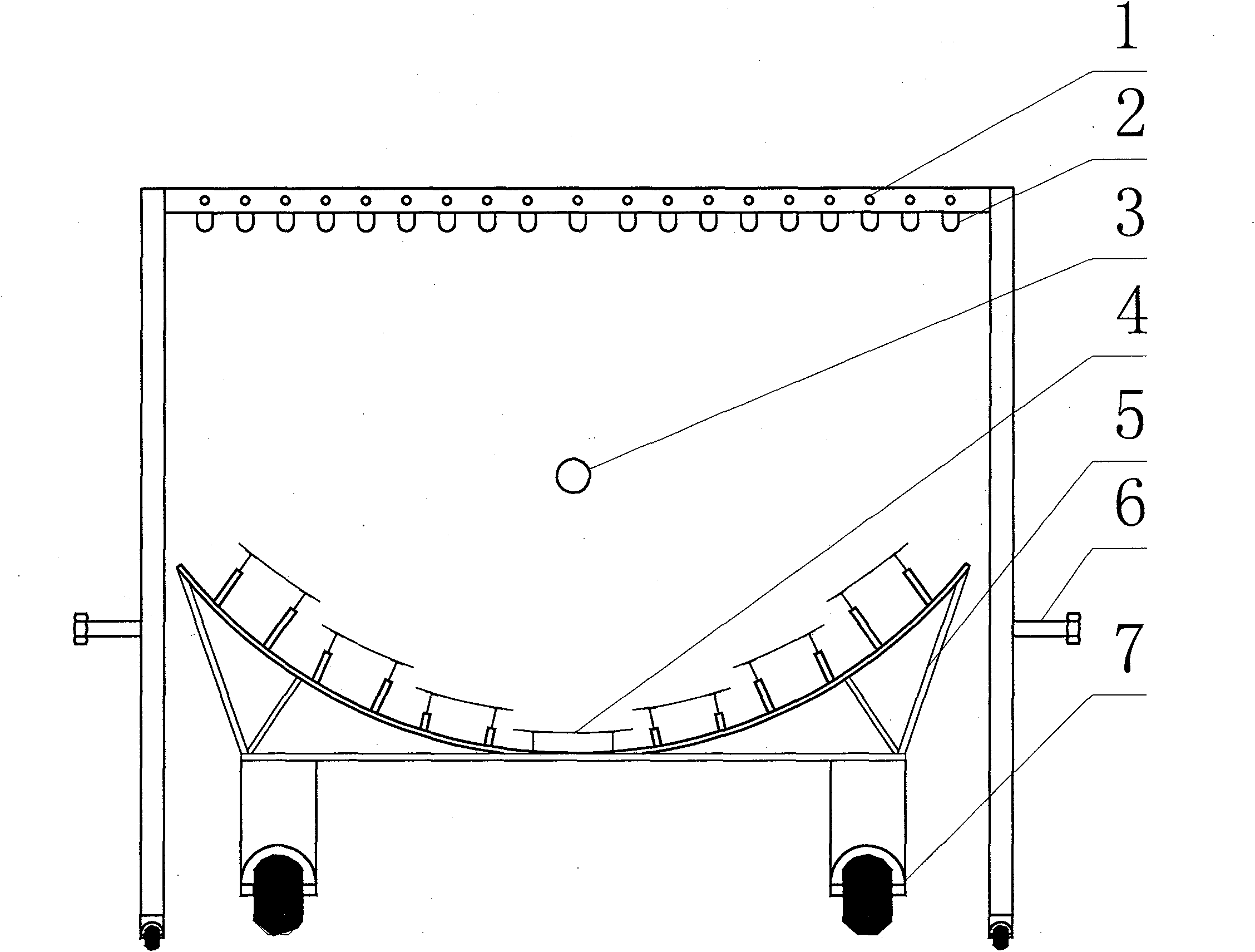
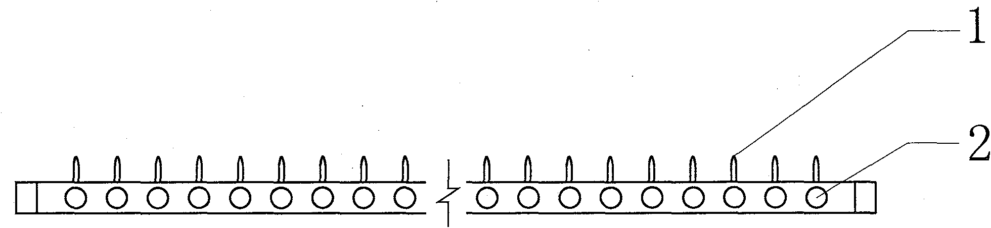
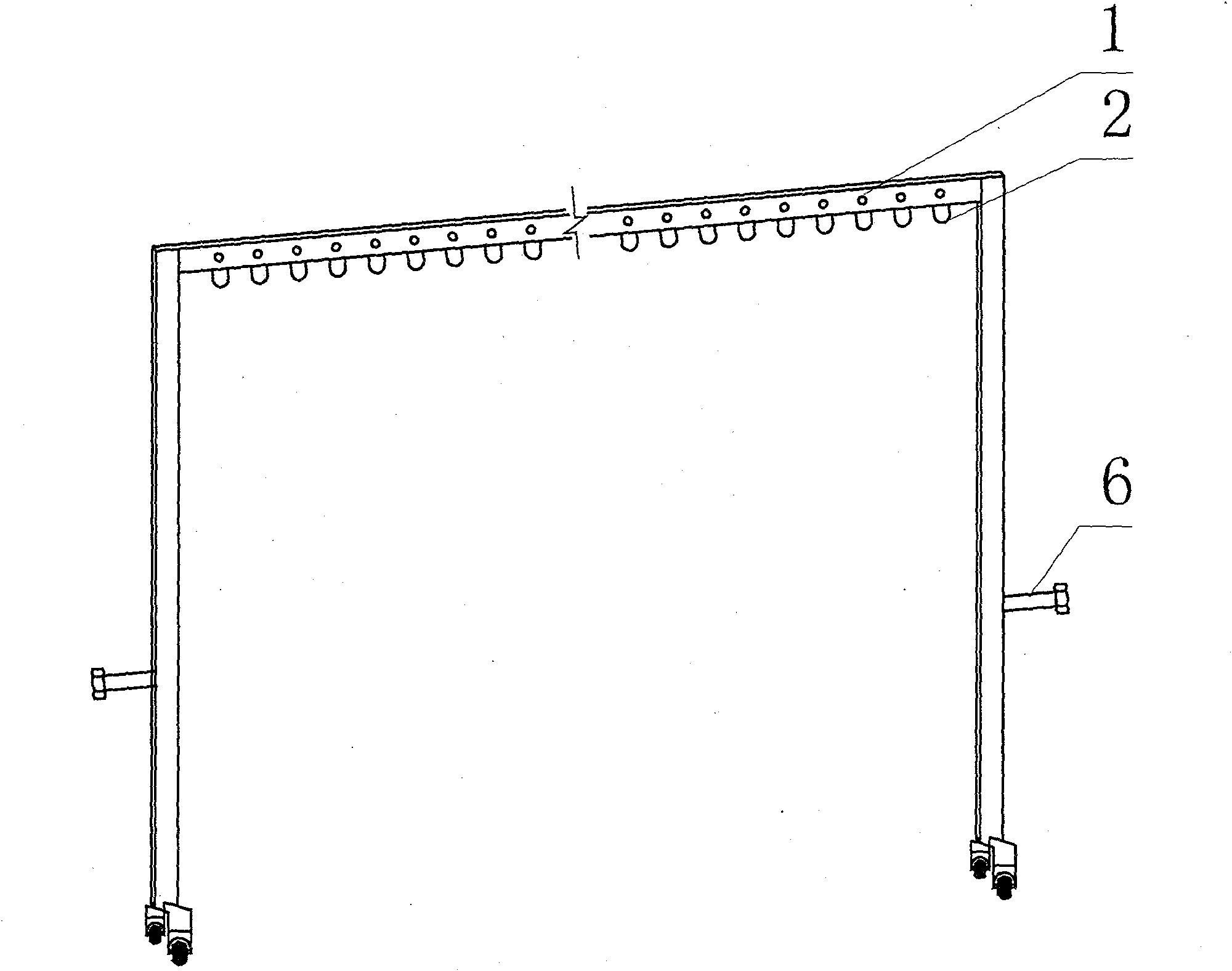
[0061] Such as figure 1 As shown, the test system of the indoor optical path includes a laser generator, a condenser to be tested, a condenser bracket and a receiver. The laser generator includes several laser head switches 1 and corresponding laser heads 2, and is supported by a support frame to a height , the support frame is a portal frame, wherein the column is a telescopic structure, the height can be adjusted by nuts 6, and the support frame is adjusted to be 7 meters wide and 8 meters high; below the laser generator is a condenser lens bracket 5, that is, the condenser lens group bracket, It is installed and fixed on the trolley 7, and the trolley 7 runs through the wheels; the condenser 4 is installed and fixed on the condenser bracket 5 to form a condenser lens group; the receiver 3 is located between the condenser bracket and the laser generator. The condensing lens group bracket is a steel structure frame, which supports the arc-shaped steel frame. There are a plura...

Embodiment 2

[0070] Such as Figure 5 As shown, the test system of the indoor optical path includes a laser generator, a condenser to be tested, a condenser bracket and a receiver. The laser generator includes several laser head switches 1 and corresponding laser heads 2, and is supported by a support frame to a height , the support frame is a portal frame, wherein the column is a telescopic structure, the height can be adjusted by the nut 6, and the support frame is adjusted to be 2 meters wide and 3 meters high; the laser generator is a condenser bracket 5, that is, a single curved surface condenser The bracket is installed and fixed on the trolley 7, and the trolley 7 runs through the wheels; the condenser 4 is installed and fixed on the condenser bracket 5; the receiver 3 is located between the condenser bracket and the laser generator. The monolithic curved surface condenser bracket is composed of a movable frame 8 controlled by an intermediate shaft. There is a hand crank at one end ...


PUM


Abstract

The invention discloses an indoor light path test system which comprises a laser generator, a condenser lens to be tested, a condenser lens bracket and a receiver, wherein the laser generator is used for shooting laser beams; the condenser lens bracket is used for mounting and fixing the condenser lens to be tested and is arranged below the laser generator; and the receiver is used as a screen of a focal spot formed by the reflected light of the condenser lens bracket and is arranged between the condenser lens bracket and the laser generator. The invention further discloses a method for testing a light path and a method for testing the energy flux density of the focal spot.

Description

technical field [0001] The invention relates to an optical path testing system, in particular to an indoor optical path testing system of a solar reflective concentrator, belonging to the technical field of solar energy utilization. Background technique [0002] Energy is an important material basis for the development of the national economy and the improvement of people's living standards. With the sustained and rapid economic growth, the limited resources of fossil energy and the environmental problems caused by development and utilization have increasingly become constraints to the sustainable development of the economy and society. factor. Accelerating the development and utilization of renewable energy is an important way and measure to solve energy and environmental problems. Solar energy is a clean, non-polluting and inexhaustible energy source. Solar power generation is one of the fastest growing renewable energy sources, and it is also the focus of countries compe...

Claims


Application Information

Patent Timeline
Patent Type & Authority Applications(China)
IPC IPC(8): G01M11/02G02B27/48
Inventor 匡荛李小燕谷伟李保庆夏苏恒
Owner SOUTHEAST UNIV
Why Eureka
Try Eureka