Axial magnetic field modulated brushless double rotor motor

A dual-rotor motor and axial magnetic field technology, applied in the direction of motors, magnetic circuit rotating parts, electromechanical devices, etc., can solve the problems of reduced operating efficiency and reduced reliability, and achieve increased reliability, reduced costs, and high torque density high effect

Active Publication Date: 2010-12-22
HARBIN INST OF TECH
View PDF2 Cites 29 Cited by
  • Summary
  • Abstract
  • Description
  • Claims
  • Application Information

AI Technical Summary

Problems solved by technology

[0004] The purpose of the present invention is to solve the problem that the rotating winding in the existing dual-rotor motor needs to introduce current through brushes and slip rings, resulting in a decrease in operating efficiency and reliability, as well as frequent maintenance of components such as brushes, and provides a A brushless dual-rotor motor with axial magnetic field modulation

Method used


Image

  • Axial magnetic field modulated brushless double rotor motor
  • Axial magnetic field modulated brushless double rotor motor
  • Axial magnetic field modulated brushless double rotor motor

Examples


specific Embodiment approach 1

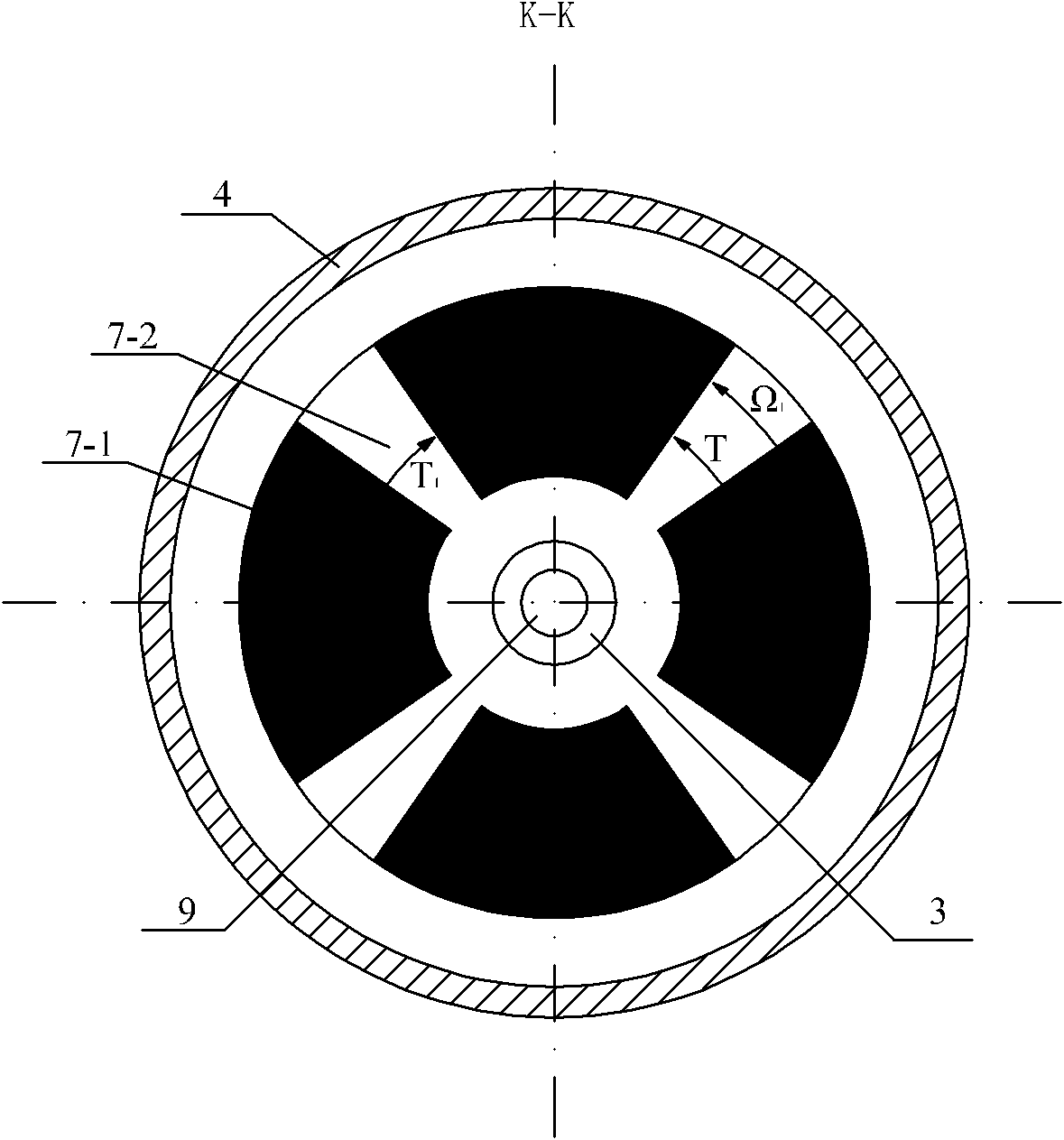
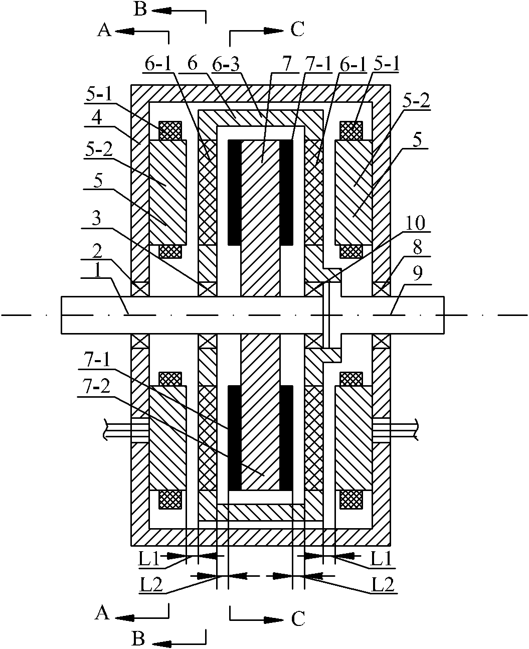
[0030] Specific implementation mode one: the following combination Figure 1 to Figure 4 Describe this embodiment, this embodiment includes housing 4, stator 5, permanent magnet rotor 7 and permanent magnet rotor output shaft 1, it also includes modulation ring rotor 6 and modulation ring rotor output shaft 9,

[0031] The end faces of the outer rings of the two stators 5 are respectively fixed on the inner walls of the left and right end faces of the housing 4, and the permanent magnet rotor 7 is fixed on the output shaft 1 of the permanent magnet rotor. One end face of the body 4 is rotationally connected, and is rotationally connected with the modulation ring rotor 6 through the second bearing 3 and the fourth bearing 10. The modulation ring rotor 6 is located between the two stators 5 and outside the permanent magnet rotor 7. The modulation ring rotor One end of the output shaft 9 is fixed on the modulating ring rotor 6, and the modulating ring rotor output shaft 9 is rota...

specific Embodiment approach 2

[0064] Specific implementation mode two: the following combination Figure 5 to Figure 8 Describe this embodiment, this embodiment includes housing 4, stator 5, permanent magnet rotor 7 and permanent magnet rotor output shaft 1, it also includes modulation ring rotor 6 and modulation ring rotor output shaft 9,

[0065] The end surface of the outer ring of the stator 5 is fixed on the inner wall of the end surface of the housing 4, the permanent magnet rotor 7 is fixed on the output shaft 1 of the permanent magnet rotor, and the output shaft 1 of the permanent magnet rotor is connected to the end surface of one side of the housing 4 through the third bearing 8 Rotationally connected, the modulation ring rotor 6 is located between the stator 5 and the permanent magnet rotor 7, one end of the modulation ring rotor output shaft 9 is rotationally connected with the permanent magnet rotor 7 through the second bearing 3, and the modulation ring rotor output shaft 9 passes through the ...


PUM


Abstract

The invention discloses an axial magnetic field modulated brushless double rotor motor, belonging to the motor field and solving the problems that the operating efficiency is lowered and the reliability is reduced because the winding rotation in a double rotor motor introduces the current through an electric brush and a slip ring, and the components, such as electric brushes and the like need to be maintained. The two stators of the invention are fixed the left end and the right end of a shell; a modulated ring rotor is positioned between the two stators and outside a permanent magnet rotor; a prime motor drives the permanent magnet rotor to rotate to form a 2n pole magnetic field; the stator is electrified to form a 2p pole magnetic field; the 2n pole magnetic field and the 2p pole magnetic field are modulated by the modulated ring rotor; q magnetic-conducting pieces and q insulated pieces are arranged on the end surface at the two sides of a stator frame of the modulated ring rotor along the peripheral direction in an interlacing manner; the relational expression that p is equal to the absolute value of the sum of hn and kq is satisfied, which is given to the load by the output shaft of the modulated ring rotor in different rotating speed; and the axial magnetic field modulated brushless double rotor motor of the motor of the invention has two structures, one structure is in axial symmetrical type, and the other structure is in axial unilateral type. The motor of the invention is used for the occasions of electric automobiles, wind power generation and torpedo drive.

Description

technical field [0001] The invention relates to an axial magnetic field modulation type brushless double-rotor motor and belongs to the field of motors. Background technique [0002] The dual-rotor motor has two rotors and rotating shafts with independent rotational speeds, which can realize dual-axis independent drive, so it has broad application prospects in electric vehicles, wind power generation, torpedo propulsion and other occasions. [0003] A common method for realizing dual-shaft drive in existing dual-rotor motors is to use the rotor of the traditional motor as one rotor and connect it to a rotating shaft, and rotate the stator of the traditional motor as another rotor and connect it to another rotating shaft. Among them, one rotating shaft is connected to the prime mover as the energy input end, and the other rotating shaft is connected to the load as the energy output end. By adjusting the frequency of the current in the rotating stator winding, the input shaft ...

Claims


Application Information

Patent Timeline
Patent Type & Authority Applications(China)
IPC IPC(8): H02K16/00H02K1/27H02K1/22H02K1/16
CPCY02T10/641Y02T10/64
Inventor 郑萍白金刚佟诚德隋义闫海媛黄永恒
Owner HARBIN INST OF TECH
Why Eureka
Try Eureka