
Medical intravenous infusion set

An intravenous infusion and medical technology, applied in the field of medical devices, can solve the problems of easy inclination, easy production of defective products, and high cost, and achieve the effects of ensuring sealing performance, improving production efficiency and low production cost.

Inactive Publication Date: 2010-12-29
柯丽红
View PDF8 Cites 16 Cited by
  • Summary
  • Abstract
  • Description
  • Claims
  • Application Information

AI Technical Summary

Problems solved by technology

At the beginning of the infusion of ordinary infusion sets, the liquid medicine flows out from the dropper through the pipeline and enters the dripping funnel. The liquid easily discharges the gas in the dropping funnel downwards to form a gas-liquid mixture into the lower infusion catheter, thus generating air bubbles. At the same time, Due to the surface tension of the inner wall of the infusion catheter, the inner wall of the infusion catheter is easy to absorb a small amount of air bubbles, and the process of removing the resulting air bubbles is difficult, time-consuming and cumbersome. If the generated air bubbles enter the patient's body, it is easy to cause air embolism and other hazards
Therefore, before the infusion, the medical staff must manually drain the air bubbles in the catheter of the infusion set as much as possible. The usual method of artificial exhaust is: after inserting the cork puncturer into the infusion bottle stopper, first hang the dripping funnel upside down. At the same time, squeeze the dripping funnel by hand to make the medicine liquid enter the dripping funnel. After a certain amount of liquid is filled with the dropping funnel, most of the air bubbles can be removed. This process of manually removing air bubbles is cumbersome and time-consuming, which is not conducive to emergency Infusion and rescue of patients
In view of the above problems, Chinese patents CN101337098A and CN101708349A respectively disclose a kind of intravenous infusion set that can be automatically exhausted, both of which are provided with an exhaust pipe or an exhaust needle that can extend into the dripping funnel on the dripping funnel cover and are installed in the dripping funnel. The air filter membrane on the opening of the exhaust pipe or the exhaust needle is combined to realize the automatic exhaust of the dropping funnel, eliminating the cumbersome and time-consuming manual air bubble removal process, but these two patent applications are due to All of them are provided with an exhaust pipe or an exhaust needle that can extend into the inner cavity of the drip funnel on the cover of the drip funnel. Due to the small diameter of the exhaust pipe or the exhaust needle, it will be adhered by the surface tension of the liquid in the drip funnel. Water droplets will block the mouth of the tube or the needle hole, which will affect the second automatic exhaust, and the exhaust pipe extending into the dropping funnel and the dropping funnel are two different materials, which will affect the observation of the infusion speed. At the same time, due to The ring frame for fixing the water-permeable and air-impermeable water-permeable filter membrane is directly installed into the dripping funnel from the opening above the dripping funnel. The ring frame is difficult to position accurately and is prone to tilting, resulting in low production efficiency, prone to defective products, and high cost. Moreover, the ring frame and the dripping funnel that fix the water-permeable and air-tight filter membrane are two different materials, and their expansion coefficients are different. There is a gap between the inner wall of the drip funnel and the ring frame, which affects the water-permeable and air-tight water-permeable filter membrane. Tightness with dripping funnel

Method used


Image

  • Medical intravenous infusion set
  • Medical intravenous infusion set
  • Medical intravenous infusion set

Examples


Embodiment Construction

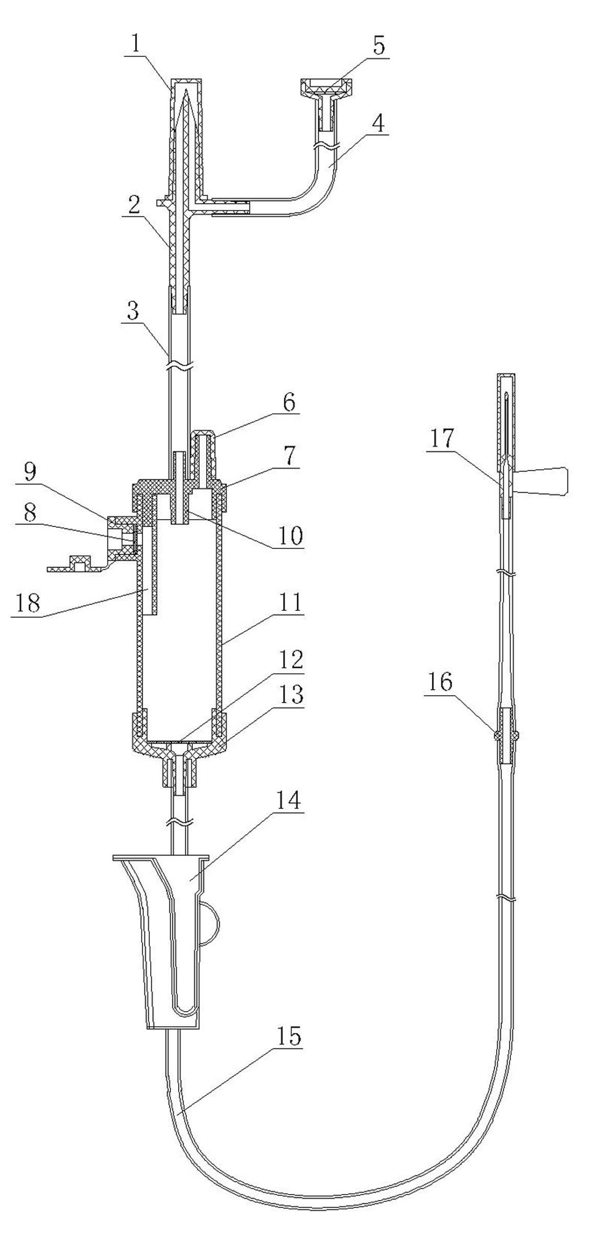
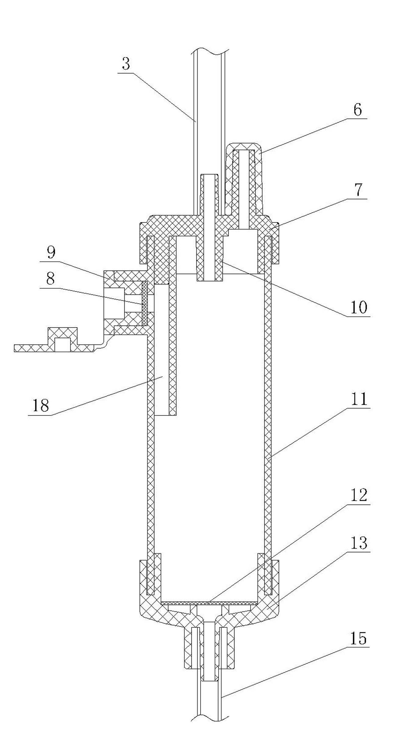
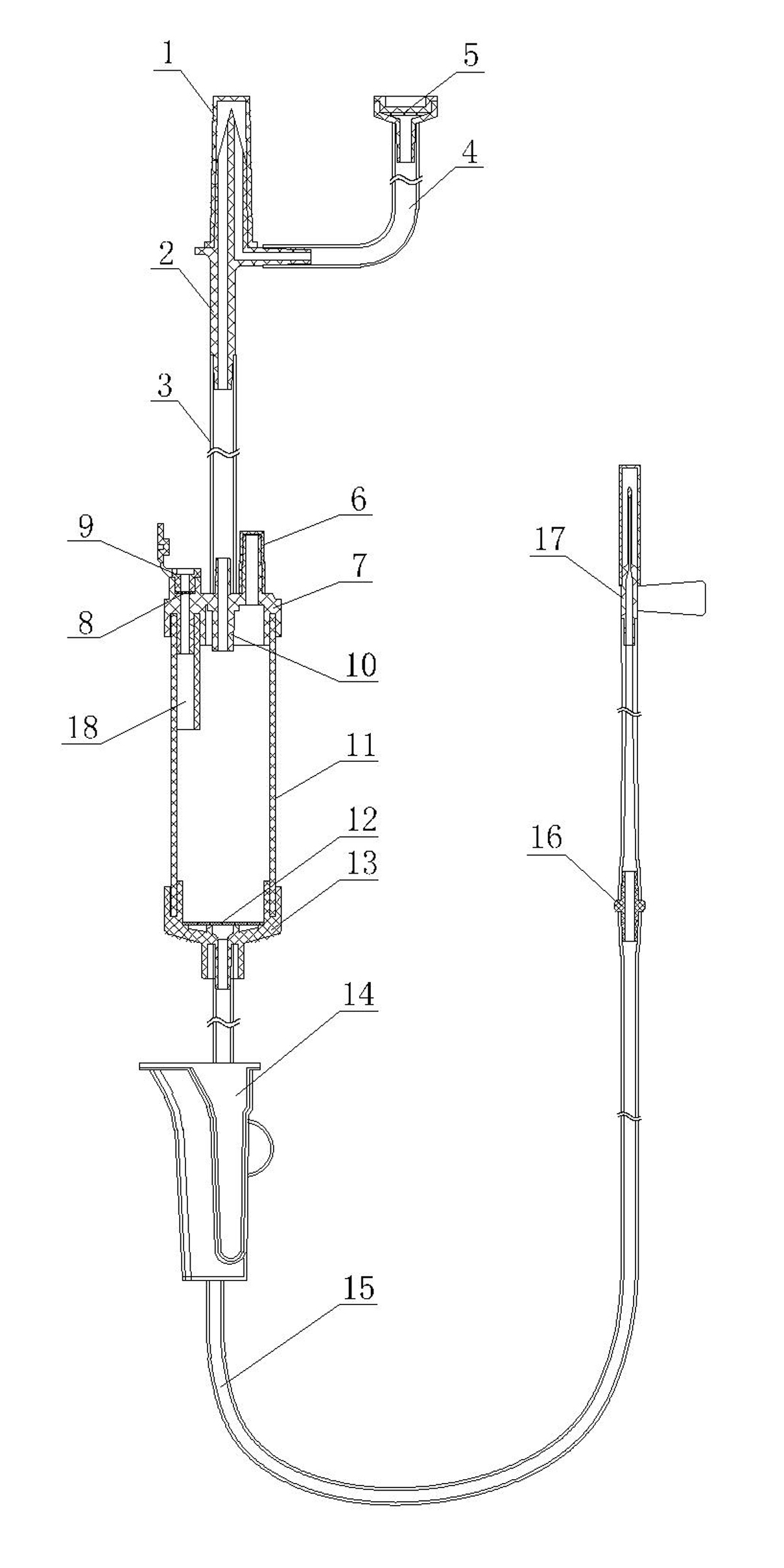
[0020] like Figure 1-Figure 8 As shown, the medical venous infusion set of the present invention includes a liquid inlet assembly, a dripping funnel 11, a liquid outlet assembly and a disposable intravenous injection needle 17 connected in sequence, wherein the sealing cover on the upper opening of the dripping funnel 11 is provided with The dripping funnel cover 7, and the dripping funnel cover 7 is provided with a dropper 10 extending into the dropping funnel 11 and a medicinal solution injection piece 6 for adding medicinal liquid, and the liquid inlet assembly passes through the infusion upper conduit 3 and the dripper 10, the upper part is connected, the liquid outlet assembly is connected with the liquid outlet below the dripping funnel 11, and the disposable intravenous injection needle 17 is connected with the outlet of the liquid outlet assembly. The dripping funnel 11 is a cavity with upper and lower ends open, and its The upper sealing cover of the lower end openin...


PUM


Abstract

The invention discloses a medical intravenous infusion set, which comprises a liquid inlet component, a dropping hopper, a liquid outlet component and a disposable intravenous injection needle connected in turn, wherein the upper opening of the dropping hopper is covered by a dropping hopper cover in a sealing way; the dropping hopper cover is provided with a dropper extending into the dropping hopper and a liquid medicine injection piece used for adding a liquid medicine; the dropping hopper is a cavity with upper and lower opening at two ends; and the lower opening is covered by a bottom cover with a liquid outlet in a sealing way. The dropping hopper is skillfully designed to have a cavity structure with the upper and lower openings, and the lower opening of the dropping hopper is provided with the bottom cover with the liquid outlet in a sealing way, so the manufacturing and processing of dual cavities between pipe walls are facilitated, and a permeable filtering membrane which is permeable and airtight is convenient to place; therefore, the sealing performance of the membrane body is ensured, the manufacturing is easy, and the production efficiency is improved. The medical intravenous infusion set has the advantages of simple structure, strong practicability, low production cost and the like.

Description

technical field [0001] The invention relates to an intravenous infusion set, in particular to a medical intravenous infusion set, which belongs to the field of medical equipment. Background technique [0002] At present, the common infusion set commonly used in the medical field consists of a bottle stopper piercer protective cover, a bottle stopper piercer, an infusion upper catheter, an exhaust catheter, an air filter, an upper dropper, a drip funnel, a flow regulator, an infusion lower catheter, It consists of liquid medicine filter, disposable intravenous infusion needle and other components. At the beginning of the infusion of ordinary infusion sets, the liquid medicine flows out from the dropper through the pipeline and enters the dripping funnel. The liquid easily discharges the gas in the dropping funnel downwards to form a gas-liquid mixture into the lower infusion catheter, thus generating air bubbles. At the same time, Due to the surface tension of the inner wall...

Claims


Application Information

Patent Timeline
IPC IPC(8): A61M5/14A61M5/38A61M5/36
Inventor 柯丽红
Owner 柯丽红
Learn More