Eureka AIR delivers breakthrough ideas for toughest innovation challenges, trusted by R&D personnel around the world.

Chelate resin tower

A chelating resin tower and chelating resin technology, applied in ion exchange, chemical instruments and methods, chemical/physical processes, etc., can solve the problems of no backwash filter device, increased maintenance time, and increased cost of rubber lining, etc. Achieve the effect of ensuring safe operation, reducing maintenance time, reducing manufacturing costs and rubber lining costs

Active Publication Date: 2012-05-02
营创三征(营口)精细化工有限公司
View PDF0 Cites 0 Cited by
  • Summary
  • Abstract
  • Description
  • Claims
  • Application Information

AI Technical Summary

Problems solved by technology

In the prior art, the chelating resin tower for the production of chlor-alkali is a flower plate clamped by a pair of large flanges on the tower body, and dozens to hundreds of filters made of ABS materials are installed on the flower plate through bolts. Correspondingly, There are many small holes on the flower plate for installing ABS filter caps, which increases the cost of the rubber lining. The equipment with this structure not only has high manufacturing costs, but also high operating costs, and because it does not have a backwash filter device, it will The good chelating resin is washed out together with the broken resin. If the backwashing intensity is high, the ABS filter cap will break, and the chelating resin will enter the electrolytic cell system, posing a threat to the ion membrane, causing the system to stop and need to be replaced. When filtering the cap, it is necessary to remove all the flanges and all the bolts on the tower body, and the upper tower section and flower plate of the tower body can only be operated after hoisting, which increases a lot of maintenance time

Method used


Image

  • Chelate resin tower
  • Chelate resin tower
  • Chelate resin tower

Examples


Embodiment Construction

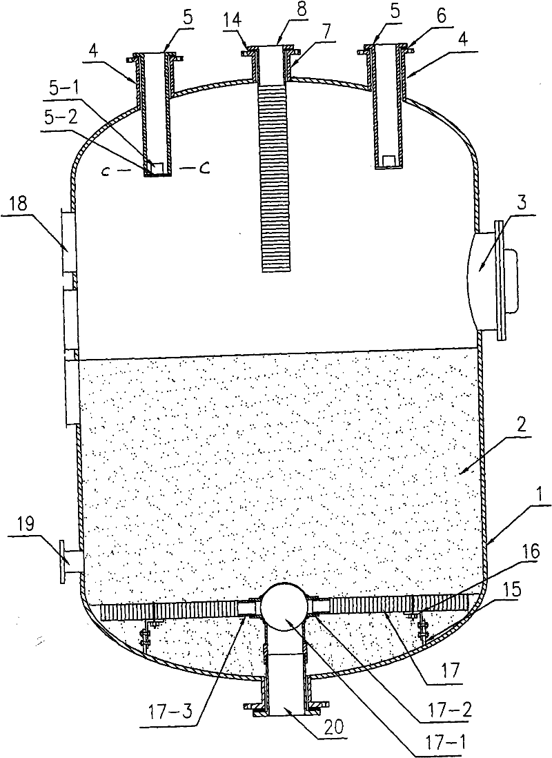
[0038] Such as figure 1 As shown, the technical solution adopted by the present invention includes a cylinder body and a tower body 1 directly welded to the upper and lower ends of the cylinder body. The tower body 1 is provided with a manhole 3, a sight glass 18 and a resin discharge hole 19. Chelating resin is housed in body 1 and forms chelating resin layer 2;

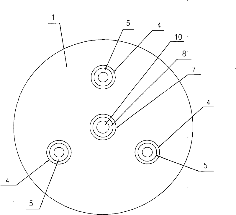
[0039] In order to make the distribution of salt water more even when entering the tower body 1, as figure 1 , figure 2 and Figure 8 As shown, three brine inlet connecting pipes 4 with flanges are welded on the top of the tower body 1, and nozzles are installed in the three brine inlet connecting pipes 4 and are provided with flanges and directly extend into the tower body 1 The inner water inlet pipe 5, the three water inlet pipes 5 are distributed at 120 degrees on the top of the tower, and the water inlet sealing rubber pad for sealing is installed between the flange of the water inlet pipe 5 and the flange ...


PUM


Abstract

The invention discloses a chelate resin tower. The invention overcomes the problems of high manufacturing cost and running cost, easy filter cap break and unsafe operation in a prior chelate resin tower. The chelate resin tower is characterized in that: three salt water admitting pipes in 120-degree distribution and a backwash exhaust pipe are welded on the top part of the tower; a backwash filter coil tray is arranged on the backwash exhaust pipe; an effluent filter tube component is arranged on the bottom of the tower body; and an effluent filter coil tray is arranged in the effluent filtertube. The chelate resin tower has the advantages that: the salt water is distributed more uniformly when entering the tower; the effluent filter tube component is capable of preventing the chelate resin from entering an electrolytic bath system with the refined salt water through a salt water exhaust pipe, thereby not only improving the availability of the chelate resin, but also avoiding the system down caused by the threat on an ionic film, ensuring the safe operation of the electrolytic bath, and reducing the troubleshooting time; and the manufacturing cost and the rubber lining cost are reduced due to the cancellation of a pattern board and the adoption of a tower structure where end plates are directly welded onto upper and lower ends of a barrel body.

Description

technical field [0001] The invention belongs to the technical field of ion exchange equipment, in particular to a chelating resin tower used in the secondary refining process of brine in the chlor-alkali production process. Background technique [0002] In the chlor-alkali production process, chlorine gas and caustic soda are produced from the electrolytic cell through the electrolysis of salt water. The requirements for the salt water are quite strict when the electrolytic cell electrolyzes the salt water. It is required that the total content of metal cations such as calcium and magnesium in the salt water should not exceed 20PPb, and the chelating resin tower is the throat equipment for brine to enter the electrolyzer, so the design of the chelating resin tower is very important. In the prior art, the chelating resin tower for the production of chlor-alkali is a flower plate clamped by a pair of large flanges on the tower body, and dozens to hundreds of filters made of AB...

Claims


Application Information

Patent Timeline
Patent Type & Authority Patents(China)
IPC IPC(8): B01J47/00
Inventor 刘至寻孙玉堂张佳兴陈光强吴丹刘旭东周永强华亮
Owner 营创三征(营口)精细化工有限公司
Why Eureka
Eureka Blog
Learn More