Isometric replaceable four-cylinder line-lock two-plate type mould clamping mechanism

A mold clamping mechanism and equal volume technology, which is applied in the field of two-plate mold clamping mechanism, can solve the problems of large processing volume of internal circulation oil cylinder, high processing precision requirements, and large size of mold clamping mechanism, so as to improve design flexibility, strength and Guaranteed rigidity, simple processing and manufacturing

Active Publication Date: 2010-12-29
BEIJING UNIV OF CHEM TECH
View PDF3 Cites 32 Cited by
  • Summary
  • Abstract
  • Description
  • Claims
  • Application Information

AI Technical Summary

Problems solved by technology

However, the processing volume of the four internal circulation oil cylinders is large, and the processing accuracy is high; the

Method used


Image

  • Isometric replaceable four-cylinder line-lock two-plate type mould clamping mechanism
  • Isometric replaceable four-cylinder line-lock two-plate type mould clamping mechanism
  • Isometric replaceable four-cylinder line-lock two-plate type mould clamping mechanism

Examples


Embodiment 1

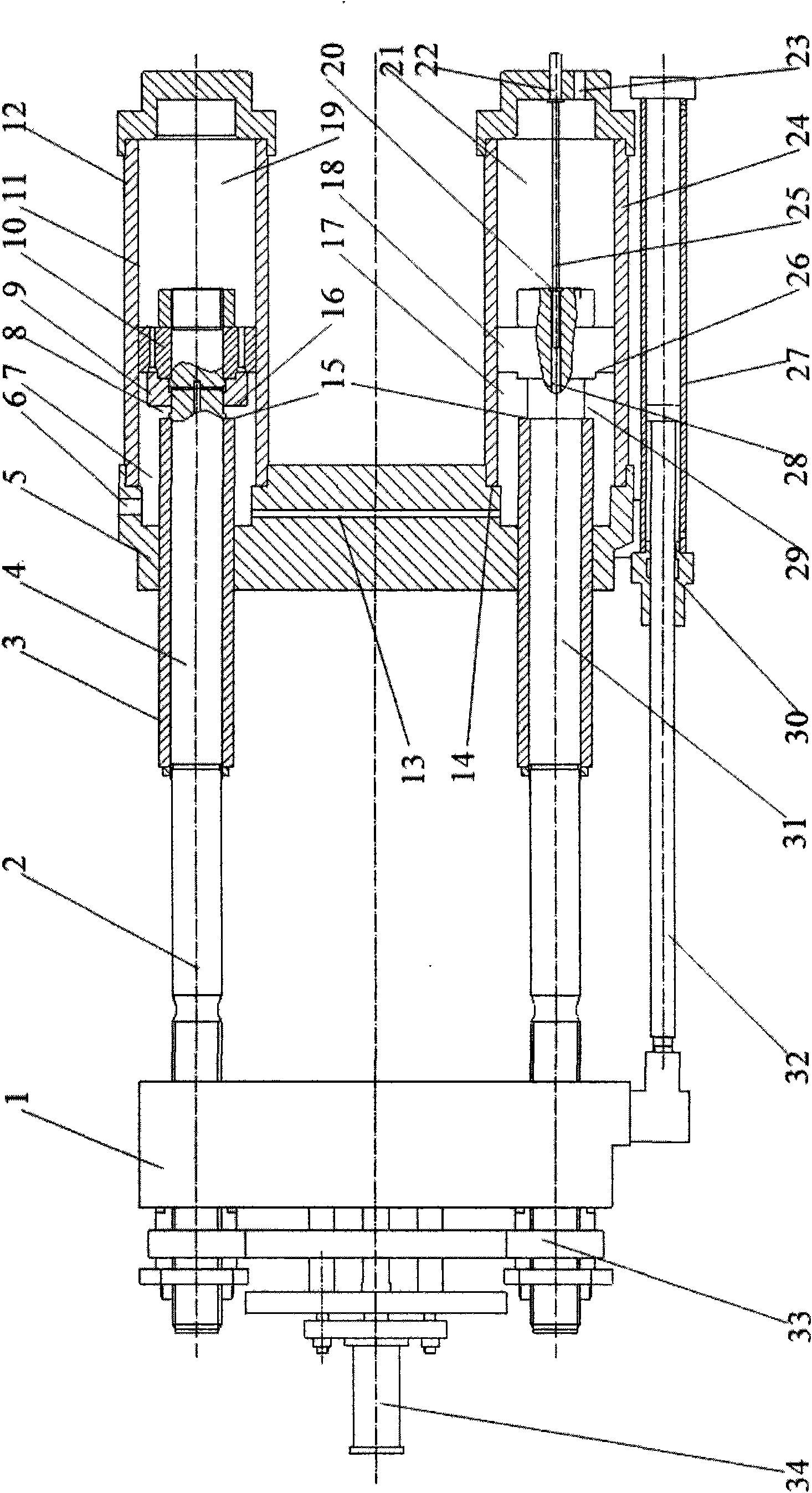
[0020] Such as figure 1 As shown, an equal-volume replacement four-cylinder direct-lock two-plate mold clamping mechanism of the present invention mainly consists of a movable template 1, a fixed template 5, a tie rod 2, a mold adjusting device 33, an ejector device 34, a mold transfer cylinder 30, an internal circulation Clamping cylinder 12, common clamping cylinder 14 and displacement sensor 22 form. The mold-moving cylinder piston rod 32 is fixed to the movable template 1, and the mold-moving cylinder body 27 is fixed on the periphery of the fixed template 5; the inner circulation mold-clamping cylinder 12 is composed of a piston rod-4 integrated with the pull rod 2, a sleeve 3, and a valve seat 9. Piston one 10 and cylinder body one 11. The sleeve 3 is set on the piston rod one 4. The distance between the end face 15 of the sleeve and the end face 16 of the slide valve is 8; Rod 2 31, sleeve 3, piston 2 18 and cylinder 2 24 are composed. The oil return chamber 21 of the ...

Embodiment 2

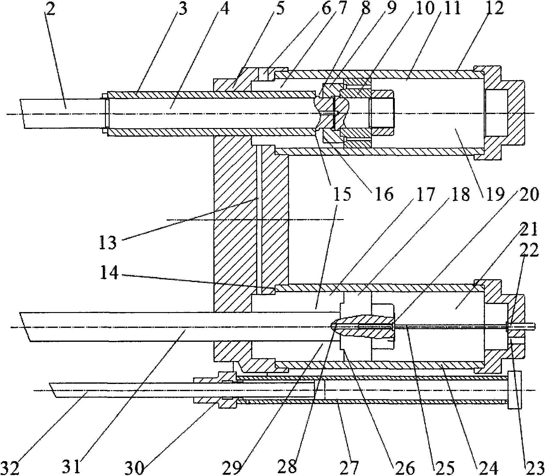
[0024] see figure 2, the structure, working principle and effect of this embodiment and embodiment 1 are basically the same. The difference is that the sleeve 3 is only provided on the two diagonal piston rods 1-4. The sleeve 3 can also be arranged on any one or three of the first piston rod 4 of the two internal circulation mold clamping cylinders 12 and the second piston rod 31 of the two ordinary mold clamping cylinders 14 . The two sleeves 3 can ensure that the volume change of the oil return cavity 19 of the inner circulation mold locking cylinder is equal to the volume change of the mold locking cavity 7 of the inner circulation mold locking cylinder and the volume change of the mold locking chamber 17 of the ordinary mold locking cylinder during the mold shifting process. Sum.

Embodiment 3

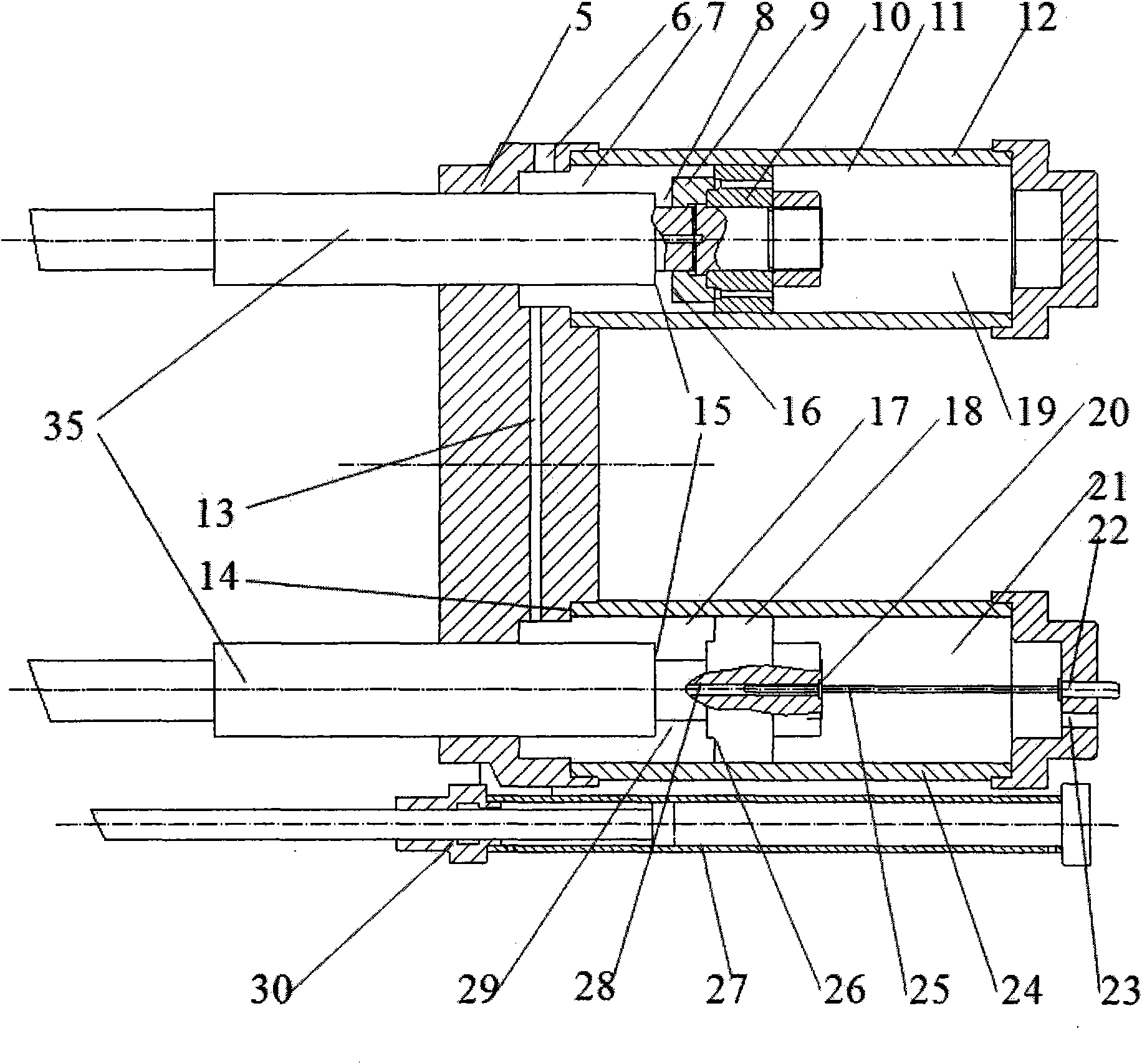
[0026] see image 3 , the structure, working principle and effect of this embodiment and embodiment 1 are basically the same. The difference is that the sleeve 3, the first piston rod 4 and the second piston rod 31 are integrated, that is, the place where the sleeve 3 is installed on the first piston rod 4 and the second piston rod 31 is thickened. The thickened part 35 of the piston rod can ensure that during the mold shifting process, the volume change of the oil return chamber 19 of the internal circulation mold clamping cylinder is equal to the volume change of the cavity 7 of the internal circulation mold clamping cylinder and the volume change of the cavity 17 of the ordinary mold clamping cylinder. and.


PUM


Abstract

The invention discloses a two-plate type mould clamping mechanism and in particular relates to an isometric replaceable four-oil cylinder line-lock two-plate type mould clamping mechanism applicable to an injection moulding machine. The mould clamping mechanism mainly comprises a movable template, a fixed template, a tension rod, a mould regulation device, a jacking mechanism, a mould moving oil cylinder, internal circulation mould locking oil cylinders, ordinary mould locking oil cylinders and a displacement sensor, wherein the number of the internal circulation mould locking oil cylinders and the number of the ordinary mould locking oil cylinders are two respectively; the internal circulation mould locking oil cylinders and the ordinary mould locking oil cylinders are diagonally and symmetrically arranged; the oil return sides of ordinary mould locking oil cylinders are communicated with air; the ordinary mould locking oil cylinders can accommodate the displacement sensor to control the movement of a template and the relative position of the template; and a volume regulation sleeve is arranged on the tension rod to guarantee that the volume change of the oil return sides of the internal circulation mould locking oil cylinders is equal to the sum of the volume change of the mould locking sides of the internal circulation mould locking oil cylinders and the volume change of the mould locking sides of the ordinary mould locking oil cylinders in a mould moving process. The mould clamping mechanism can meet the requirements of the injection moulding machines of various specifications, saves material and energy, reduces the processing difficulty and guarantees the stable performance.

Description

technical field [0001] The invention relates to a mold clamping mechanism, in particular to a two-plate mold clamping mechanism applicable to injection molding machines. Background technique [0002] With the improvement of people's requirements for the use of plastic products, the wall thickness of the products is getting thinner and the strength requirements are getting higher and higher, and the molds are becoming more complicated, and higher production efficiency is also required. Therefore, a precision injection molding machine that satisfies various functions and is even more conducive to mold protection will become more and more important, and the key to determining the above-mentioned performance of an injection molding machine is its mold clamping mechanism. [0003] The mold clamping mechanism of injection molding machine mainly includes two kinds of traditional full hydraulic mold clamping mechanism and toggle type mold clamping mechanism. The hydraulic system of...

Claims


Application Information

Patent Timeline
IPC IPC(8): B29C33/24B29C45/67B29C45/76
Inventor 谢鹏程焦志伟丁玉梅安瑛杨卫民王兴天
Owner BEIJING UNIV OF CHEM TECH
Why Eureka
Try Eureka