
Blowing slag-removing equipment for molten iron pretreatment

A technology of molten iron pretreatment and equipment, applied in casting equipment, metal processing equipment, mechanical cleaning, etc., can solve the problems of iron leakage accident maintenance and replacement, inconvenience, serious environmental heat radiation, etc., to reduce iron loss, good economic benefits, The effect of shortening the slag removal time

Active Publication Date: 2010-12-29
BAOSTEEL ENG & TECH GRP
View PDF2 Cites 22 Cited by
  • Summary
  • Abstract
  • Description
  • Claims
  • Application Information

AI Technical Summary

Problems solved by technology

In order to improve the slag removal effect, some domestic steel mills adopt the bottom (side) blowing auxiliary slag removal process of the molten iron tank, but there are many problems in the development process, such as serious erosion of the side wall of the molten iron tank, shortened life of the venting brick and the molten iron tank, and iron leakage Accidents and the inconvenience of maintenance and replacement
There are also steel mills that add a slag blowing device to the slag remover body, but the effect of slag removal is not ideal due to insufficient depth of insertion of molten iron, severe environmental heat radiation, etc.

Method used


Image

  • Blowing slag-removing equipment for molten iron pretreatment
  • Blowing slag-removing equipment for molten iron pretreatment
  • Blowing slag-removing equipment for molten iron pretreatment

Examples


Embodiment Construction

[0023] The present invention will be described in detail below in conjunction with the accompanying drawings and embodiments.

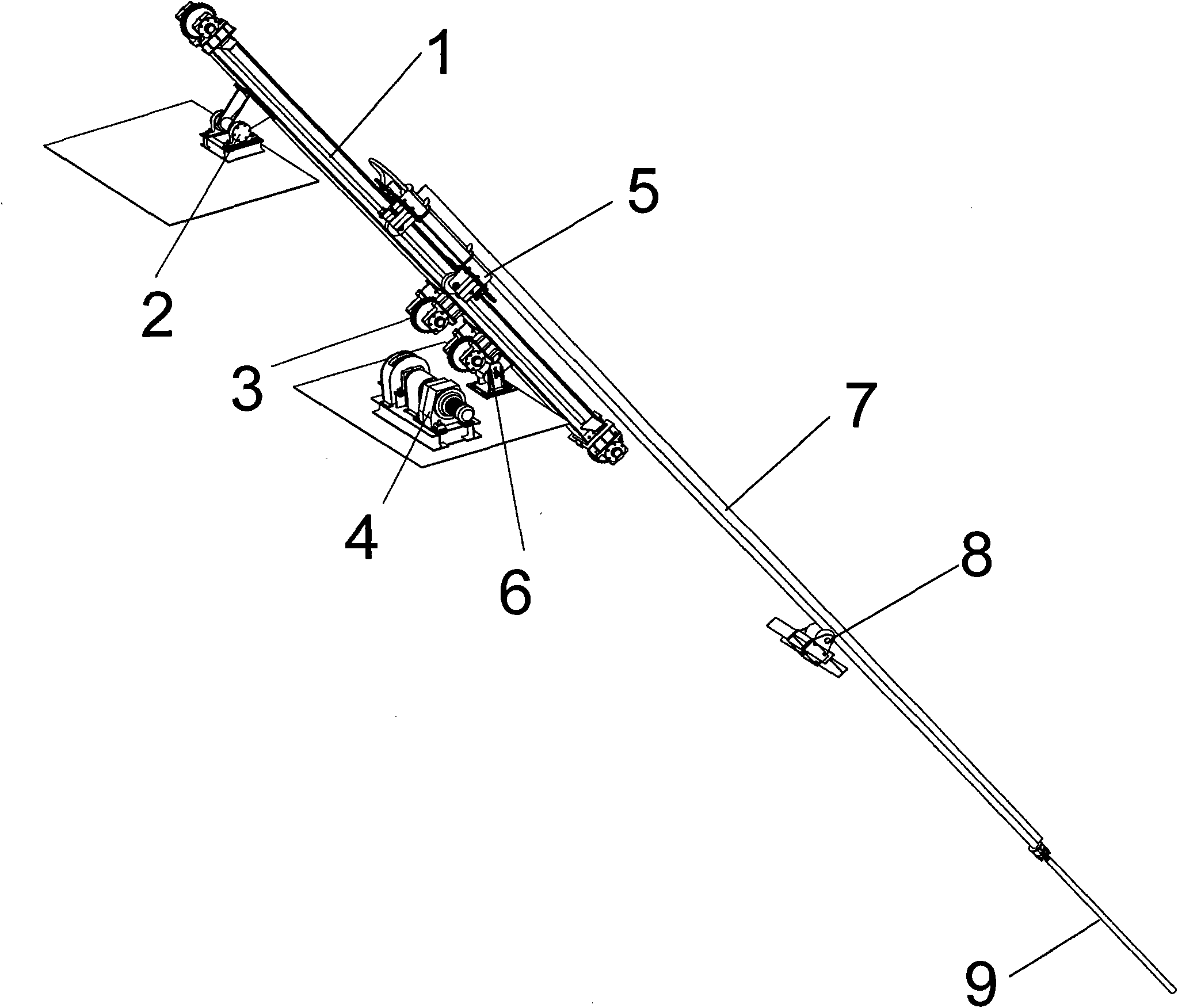
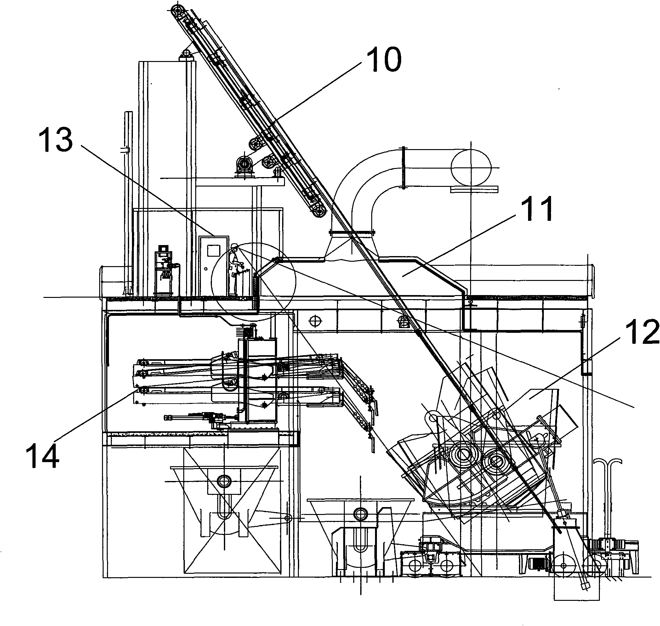
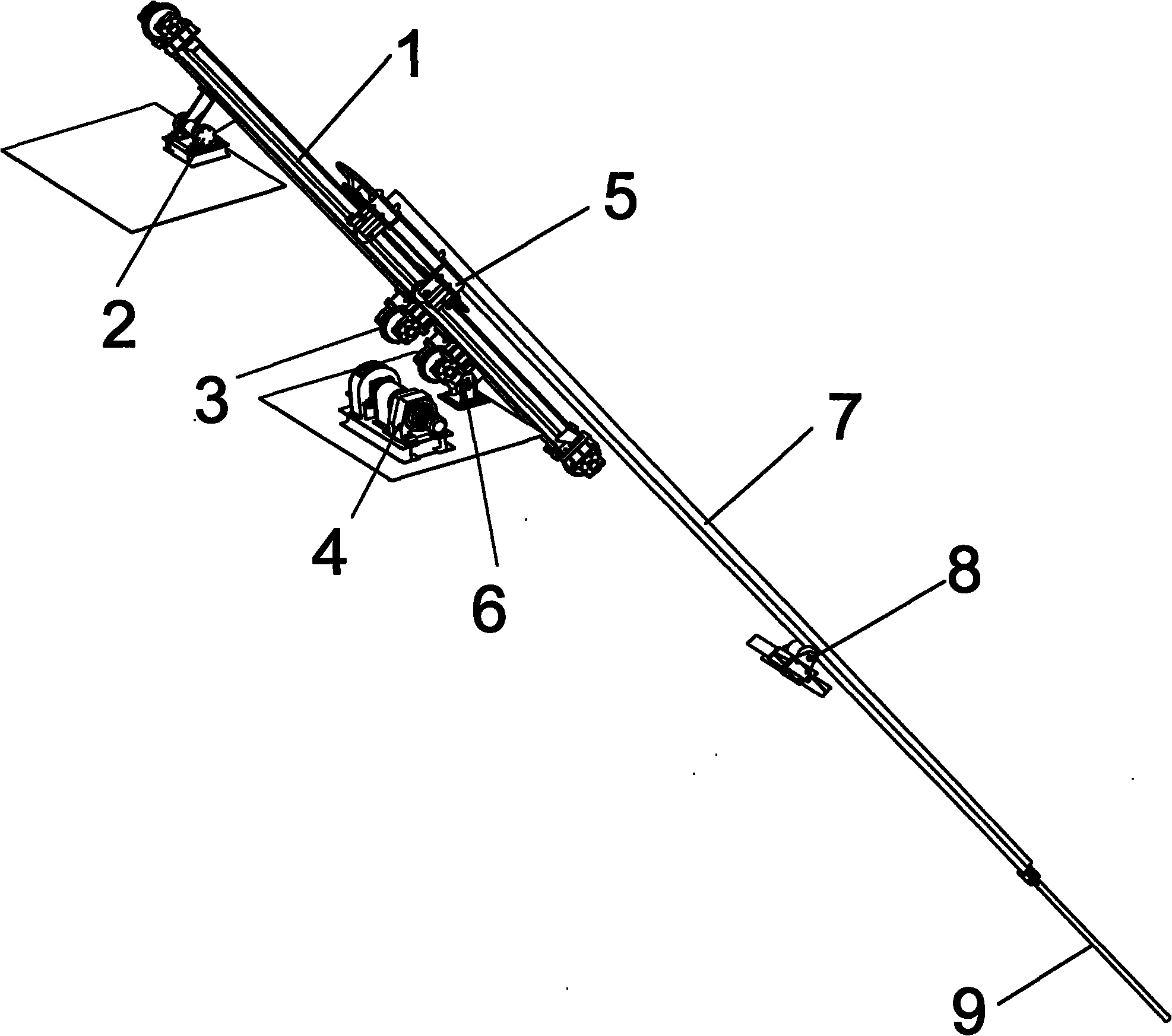
[0024] see figure 1 with figure 2 , the present invention provides a kind of hot metal pretreatment air blowing slag removal equipment, which is set on the molten iron tank slag removal machine 14 platform, mainly composed of guide rail 1, slewing support 2, guide sprocket 3, lifting drive device 4, lifting trolley 5. It is composed of adjustable support 6, air blowing rod 7, guide roller 8, refractory section 9 and air blowing slag removal device 10.

[0025] The guide rail 1 is obliquely arranged on the top of the molten iron tank 12, the lifting trolley 5 is arranged on the guide rail 1, and the lifting drive device 4 drives the lifting trolley 5 to move up and down along the guide rail 1 through the guide sprocket 3. The blowing rod 7 is arranged on the lifting trolley 5, and the refractory section 9 is connected to the blowing rod 7 bottoms. ...


PUM


Abstract

The invention relates to blowing slag-removing equipment for molten iron pretreatment, which is arranged on a platform of a slag-raking machine of a molten iron tank. The blowing slag-removing equipment comprises a guide rail, a rotary bearing, an adjustable bearing, a guide roll, a guide chain wheel, an elevating drive unit, an elevating trolley, a blowing rod and a refractory material section, wherein, the guide rail is arranged slantwise above the molten iron tank; the elevating trolley is arranged on the guide rail; the elevating drive unit drives the elevating trolley to move up and down along the guide rail through the guide chain wheel; the rotary bearing is connected with the upper part of the guide rail, the adjustable bearing is connected with the middle part of the guide rail, and the guide roll is arranged at the lower part of the guide rail; the rotary bearing and the adjustable bearing are fixed on the platform of the slag-raking machine; and the blowing rod is arranged on the elevating trolley and the refractory material section is connected with the lower part of the blowing rod. When the slag-raking machine runs, the blowing rod is inserted in ladle for blowing nitrogen; and during the slag-removing process, the slag quantity is continuously reduced and an exposed surface of molten iron is increasingly enlarged until the slag is almost entirely removed. The blowing slag-removing equipment can shorten the slag-removing time by 2 minutes, lower the iron loss by over 20% and achieve better economic benefit.

Description

technical field [0001] The invention relates to molten iron pretreatment, in particular to an air blowing slag removal device during the molten iron pretreatment. Background technique [0002] At present, most of the hot metal pretreatment in domestic and foreign steelworks adopts the process of desulphurization and dephosphorization after blowing or stirring method and then removing slag. The injection or stirring process determines the level of sulfur and phosphorus in the molten iron at the end of the treatment. The slag removal process is an important means to remove the slag after desulfurization and phosphorus treatment from the molten iron, and is the main factor determining the total amount of sulfur and phosphorus in the furnace. Therefore, it is very necessary to adopt advanced slag removal equipment and technology to control sulfur and reduce production costs in the steelmaking system. In order to improve the slag removal effect, some domestic steel mills adopt t...

Claims


Application Information

Patent Timeline
IPC IPC(8): C21C1/00C21C7/072B22D43/00
Inventor 俞文燕孟海平薛一晟胡建勋章文超
Owner BAOSTEEL ENG & TECH GRP
Learn More