Supercharge Your Innovation With Domain-Expert AI Agents!

Transmission device with differential function

A technology of transmission and function, applied in the field of transmission with differential function, can solve the problems of general products without suitable structure, difficult assembly and maintenance, complex structure and components, etc. And the effect of simplified components and easy assembly

Inactive Publication Date: 2010-12-29
王骏瑞
View PDF5 Cites 2 Cited by
  • Summary
  • Abstract
  • Description
  • Claims
  • Application Information

AI Technical Summary

Problems solved by technology

However, the differentials currently used on the market mainly use bevel gear sets as the differential structure, which not only has complex structures and components, but also has defects such as difficult assembly and maintenance, large power loss, and high cost.
[0005] This shows that above-mentioned existing general vehicle transmission device obviously still has inconvenience and defect in structure and use, and demands urgently further improving
In order to solve the above-mentioned problems, the relevant manufacturers have tried their best to find a solution, but for a long time no suitable design has been developed, and the general product has no suitable structure to solve the above-mentioned problems. This is obviously the relevant industry. Urgent problem

Method used


Image

  • Transmission device with differential function
  • Transmission device with differential function
  • Transmission device with differential function

Examples


Embodiment Construction

[0034] In order to further explain the technical means and effects of the present invention to achieve the intended purpose of the invention, the specific implementation, structure, Features and their functions are described in detail below.

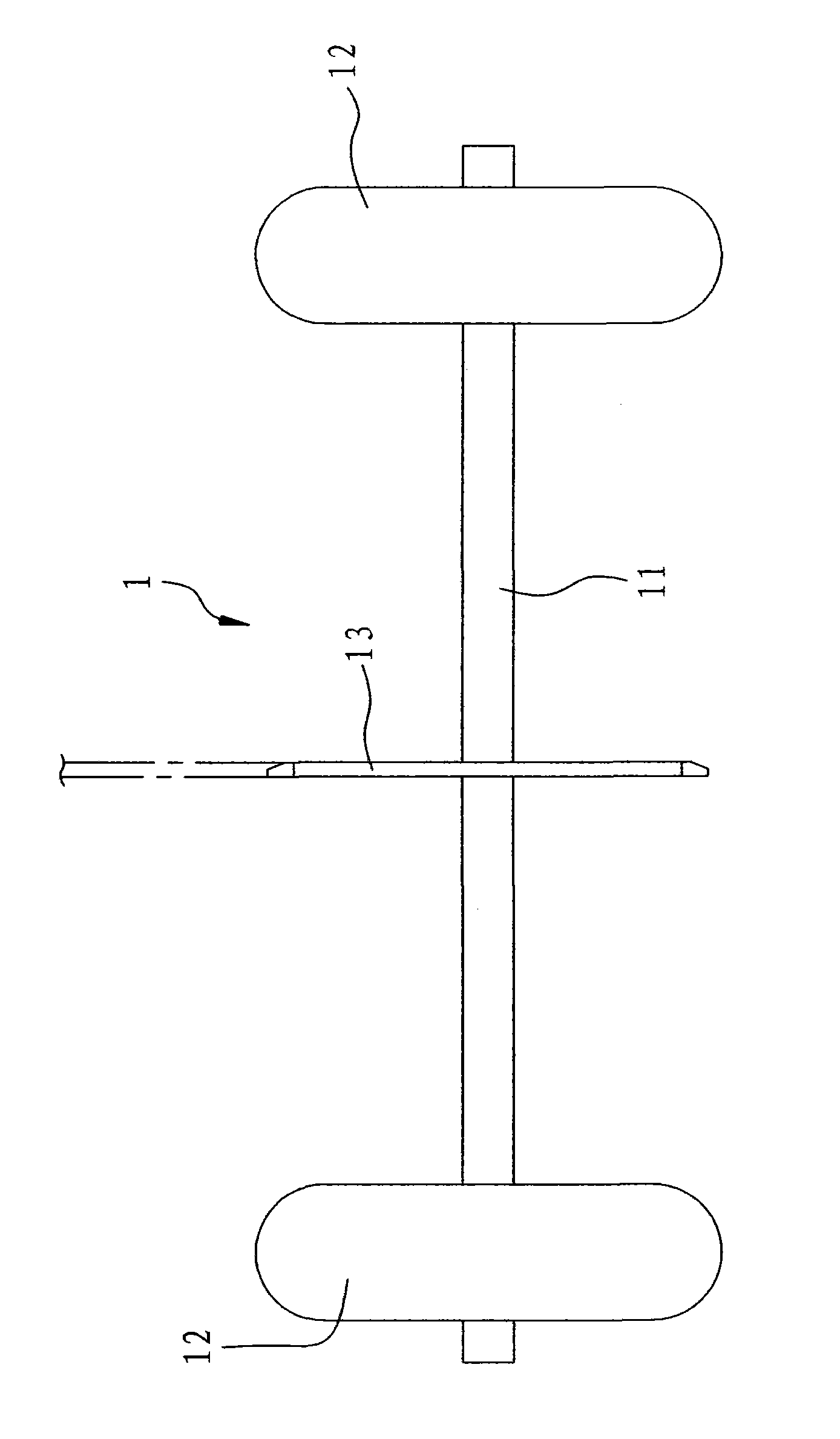
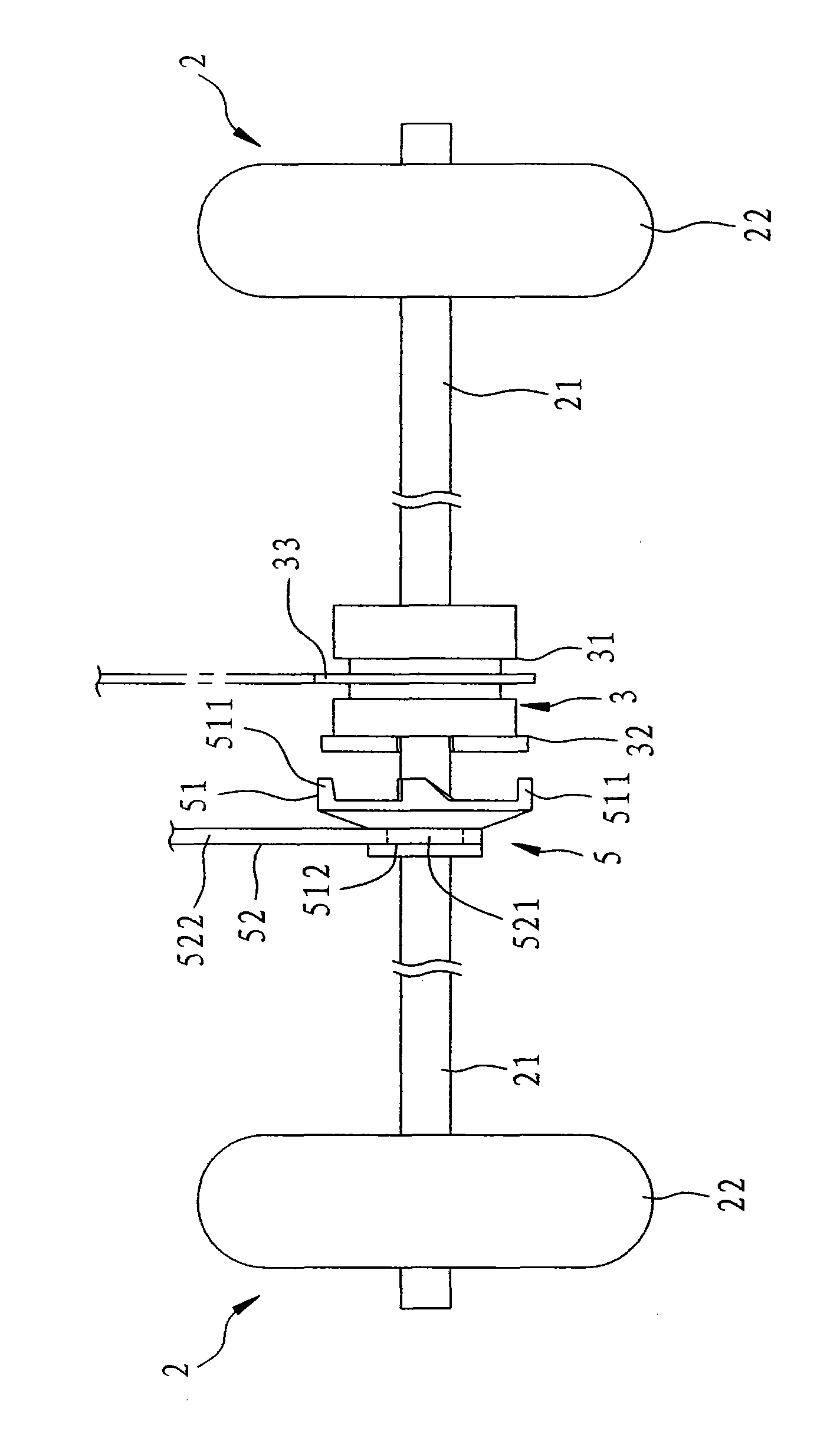
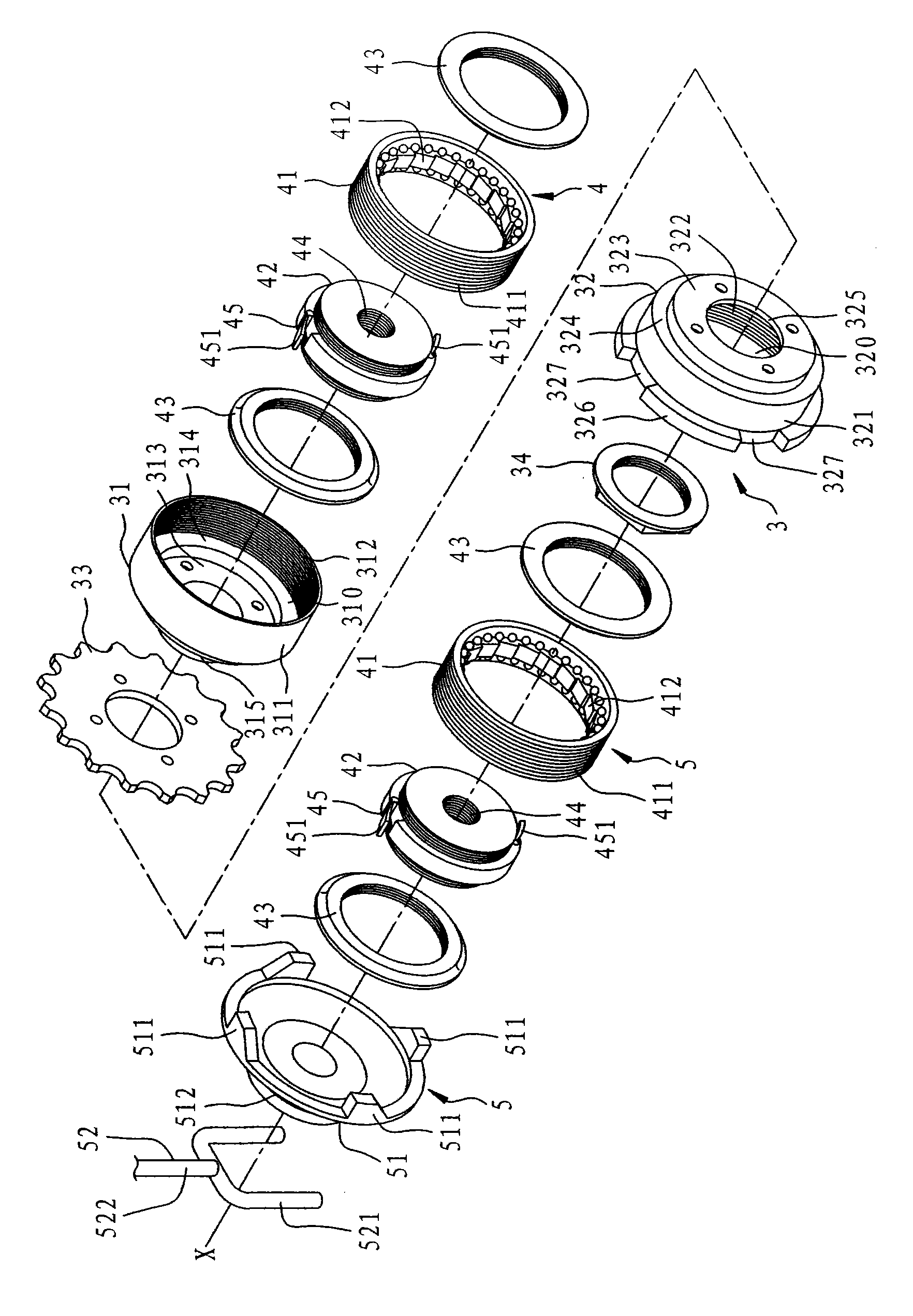
[0035] see figure 2 , a preferred embodiment of the transmission device with differential function of the present invention is used to drive two wheel sets 2 . The aforementioned wheel set 2 respectively has a wheel shaft 21 and a wheel 22 coaxially rotating with the wheel shaft 21 . refer to image 3 , Figure 4 ,and Figure 5 , the transmission device with differential function includes a bushing 3, two one-way ratchets 4, and a reversing unit 5.

[0036]The shaft sleeve 3 has a first shell seat 31 , a second shell seat 32 , a passive element 33 , and a nut 34 . The first shell seat 31 has an annular wall 311 surrounding an axis X and defining a groove 310, an internal thread segment 312 formed on an inner surface of the annular...


PUM


Abstract

The invention relates a transmission device with a differential function, which is used for driving two wheel shafts. The transmission device comprises a shaft sleeve which can be driven by a power source to rotate around an axial line and two unidirectional ratchets which are fixedly arranged at both sides of the shaft sleeve and are respectively fixedly connected with the wheel shafts to form linkage. With the rotation of the shaft sleeve, the unidirectional ratchets can drive the wheel shafts to synchronously rotate in the forward direction, and can permit one of the wheel shafts to idle in the forward direction in an asynchronous condition. Thus, based on the special design of the unidirectional ratchets, the invention enables the wheel shafts rotating in the same direction to rotate at different rotation speeds, thereby maintaining the steering stability.

Description

technical field [0001] The invention relates to a transmission device, in particular to a transmission device with a differential function for driving two wheel sets and generating a speed difference. Background technique [0002] see figure 1 Taking the transmission device 1 of a general vehicle (not shown) as an example, it mainly includes a wheel shaft 11, two wheels 12 that are arranged at two ends of the wheel shaft 11 and rotate coaxially with the wheel shaft 11, and are coaxial with the wheel shaft 11. A passive member 13 that the shaft rotates and is used to transmit power. Thereby, when the driven member 13 is driven by a power source to drive the wheel shaft 11 to rotate, the aforementioned wheels 12 and the wheel shaft 11 can be rotated synchronously to achieve the purpose of driving the vehicle. [0003] However, when the vehicle is turning, the path taken by the inner wheel 12 is shorter and the path taken by the outer wheel 12 is longer, so that the left and ...

Claims


Application Information

Patent Timeline
IPC IPC(8): F16D41/12
Inventor 王骏瑞
Owner 王骏瑞
Features
  • R&D
  • Intellectual Property
  • Life Sciences
  • Materials
  • Tech Scout
  • Unparalleled Data Quality
  • Higher Quality Content
  • 60% Fewer Hallucinations
Learn More