Burner for main burning furnace of sulfur recovery unit

A sulfur recovery and burner technology, applied in the direction of gas fuel burners, burners, combustion methods, etc., can solve the problems of slow mixing process, combustion stability and temperature field distribution, slow temperature rise of main jet, etc., to achieve Effects of improving combustion stability, increasing total sulfur generation rate, and reducing pressure drop loss

Inactive Publication Date: 2010-12-29
SOUTHWEST PETROLEUM UNIV
View PDF6 Cites 8 Cited by
  • Summary
  • Abstract
  • Description
  • Claims
  • Application Information

AI Technical Summary

Problems solved by technology

The structure of the active burner can basically realize the strong combustion of the gas in the furnace, but there are still the following deficiencies in the secondary mixing of the gas in the furnace, the temperature rise rate of the main jet, and the energy consumption of the device: 1. The structural characteristics of the burner cause the main jet to appear The airflow pattern of air-enveloped acid gas
This mixing process is relatively slow, which is unfavorable to the formation of elemental sulfur; 2. Due to the high flow rate of the main jet and the slow mixing speed of the gas inside and outside the jet, the temperature rise of the main jet is slow
Especially in the furnace acid gas flow rate or H 2 When the S content decreases, the temperature rise rate of the main jet will be slower, which will have a greater impact on the combustion stability and temperature field distribution in the furnace; can be more

Method used


Image

  • Burner for main burning furnace of sulfur recovery unit
  • Burner for main burning furnace of sulfur recovery unit
  • Burner for main burning furnace of sulfur recovery unit

Examples


Embodiment Construction

[0018] The present invention will be further described below with reference to the accompanying drawings and embodiments.

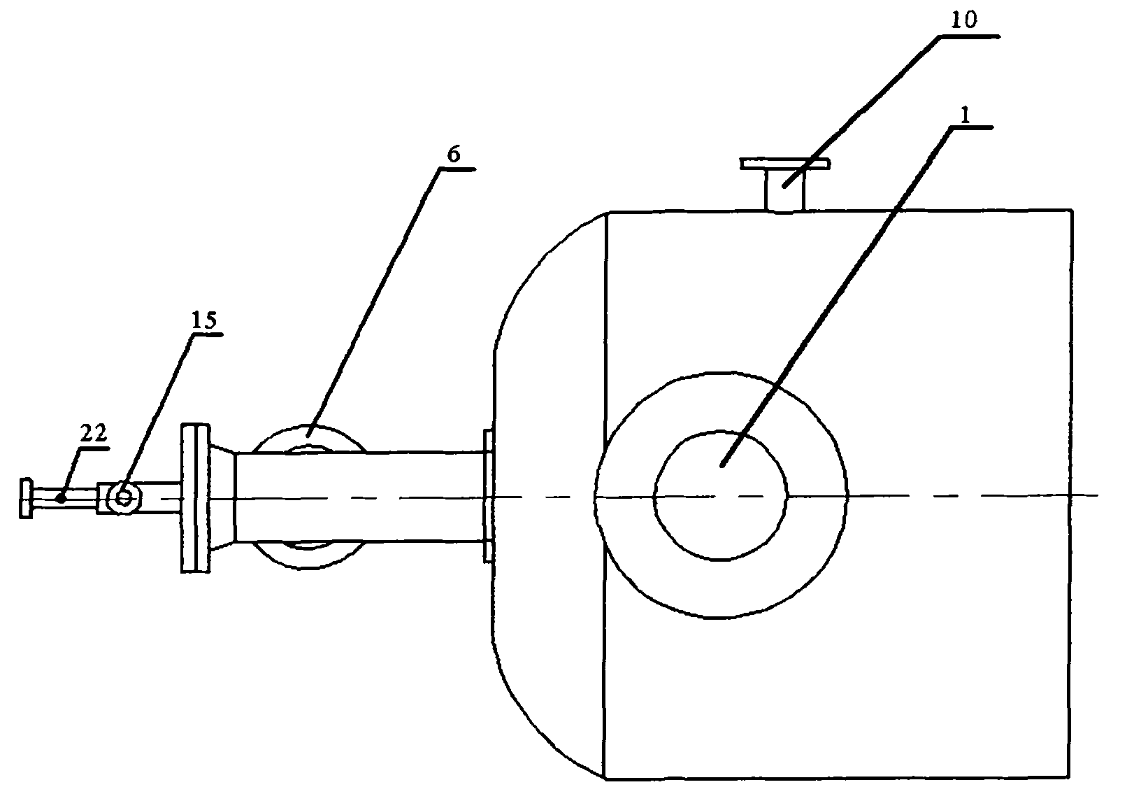
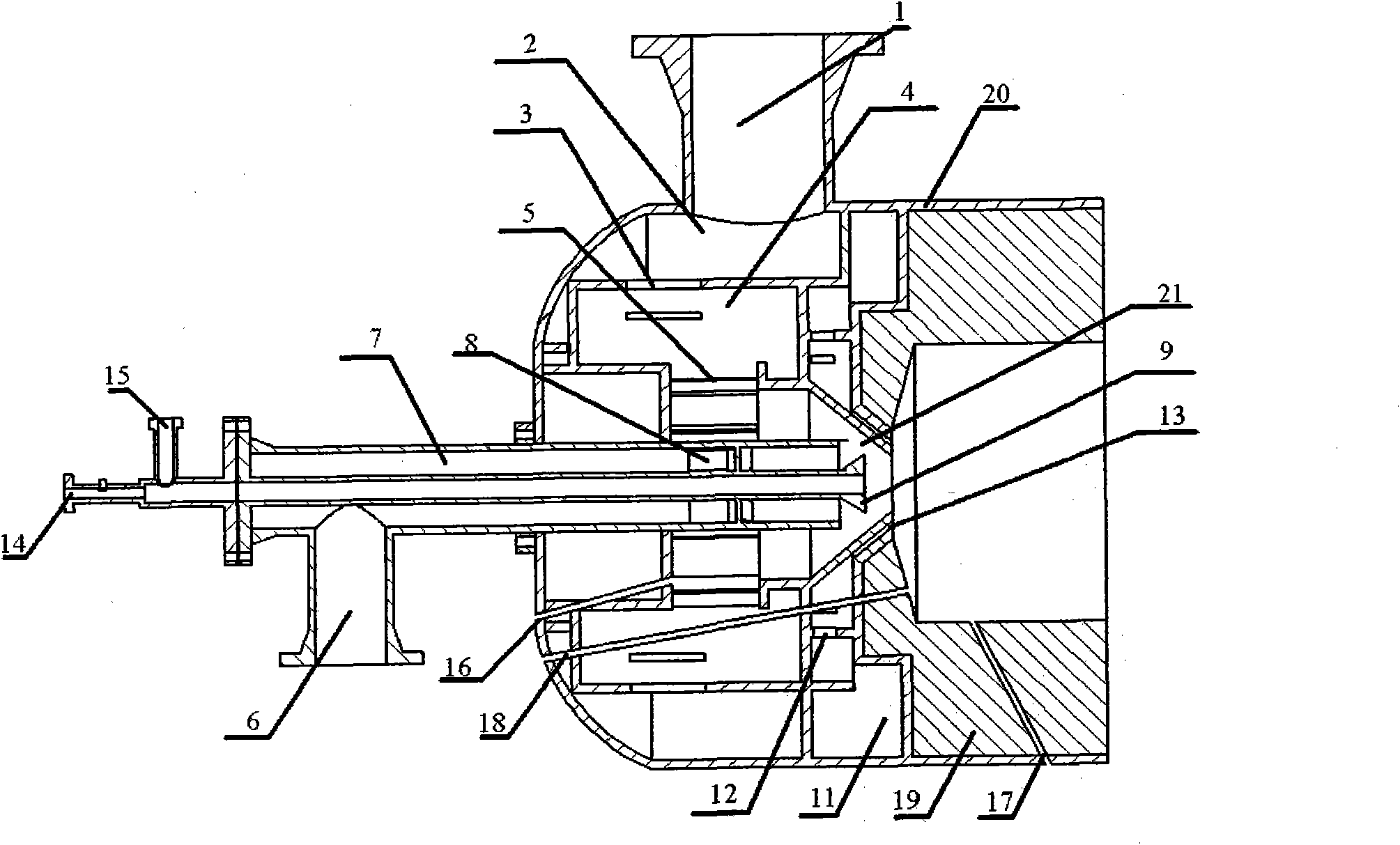
[0019] like figure 1 , figure 2 shown.

[0020] The burner of the present invention is divided into three parts: an air swirl device, an acid gas inlet device and an accessory device of the burner. The following are respectively expressed as follows:

[0021] 1. Air swirl device

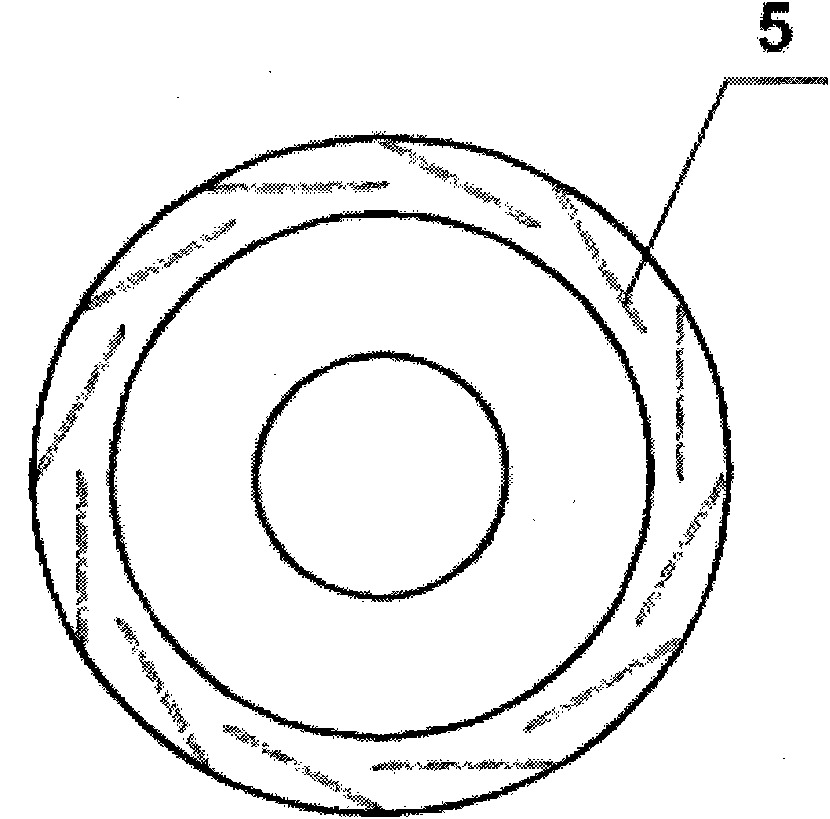
[0022] The air swirling device mainly includes an air inlet 1, an air chamber cavity 2, an air chamber perforated plate 3, an air chamber chamber 4, and an air guide vane 5. Its main function is to realize an air jet with high swirling characteristics. The air is introduced into the air inlet 1 by the blower, and is blocked by the perforated plate 3 of the air chamber, and the air quickly fills the entire cavity 2 of the air chamber. Afterwards, it enters the air chamber cavity 4 relatively uniformly through the air chamber perforated plate 3 . After the air enters the ai...


PUM


Abstract

The invention relates to a burner for a main burning furnace of a sulfur recovery unit of a process for natural gas sulfur recovery and tail gas treatment. The burner adopts a high swirling device to form swirling jet flows in the furnace and has the characteristics of high-efficiency mixing, stable burning, energy saving and consumption reduction. The technical scheme is that the burner consists of an air swirling device, a sour gas inlet device and a burner attachment, wherein the air swirling device is provided with an air inlet, an air chamber outer cavity, an air chamber porous plate, an air chamber inner cavity and an air guide vane; the sour gas inlet device comprises a central sour gas inlet and an outer ring sour gas inlet; the central sour gas inlet is provided with a sour gas inlet pipe, an annular chamber, a sour gas swirling vane and a conical nozzle; the outer ring sour gas inlet is provided with an outer ring sour gas inlet pipe, a sour gas chamber outer cavity, a sour gas chamber porous plate and an outer ring sour gas spout; and the burner attachment is provided with a burning torch inlet, a fuel gas inlet, a premixing chamber and a shell. The burner can improve the total sulfur production rate in the furnace, reduce the pressure drop loss in the furnace, and is used for the sulfur recovery unit.

Description

technical field [0001] The invention relates to a burner of a main combustion furnace of a sulfur recovery device used in a natural gas purification sulfur recovery and tail gas treatment process. Background technique [0002] In the Claus sulfur recovery process, the efficient mixing of the gas in the main combustion furnace is an important guarantee for achieving strong combustion in the furnace. In the general process, about 1 / 3 of the H in the main combustion furnace 2 Combustion of S to SO 2 , the remaining H 2 S and product SO 2 Elemental sulfur is further generated. [0003] 2H 2 S+3O 2 =2SO 2 +2H 2 O (1) [0004] 2H 2 S+SO 2 =3 / 2S 2 +2H 2 O (2) [0005] The burner is the core component in the main combustion furnace. Existing burners mostly use high swirl devices to achieve strong combustion of gas in the furnace. The structure of the active burner can basically achieve strong combustion of the gas in the furnace, but there are still the following def...

Claims


Application Information

Patent Timeline
IPC IPC(8): F23D14/02F23D14/46F23D14/48F23D14/70
Inventor 艾志久吴昌蒋静游国庆常宏岗陈昌介何金龙
Owner SOUTHWEST PETROLEUM UNIV
Why Eureka
Try Eureka