Method for manufacturing laminated rotor and stator

A processing method, stator and rotor technology, applied in the manufacture of stator/rotor body, etc., can solve the problems of rotor cylindricity error, high labor intensity, low processing efficiency, etc.

Inactive Publication Date: 2010-12-29
YANGZHOU FORGING MACHINE TOOL
View PDF1 Cites 11 Cited by
  • Summary
  • Abstract
  • Description
  • Claims
  • Application Information

AI Technical Summary

Problems solved by technology

But there are still the defects of low processing efficiency and high labor intensity
In addition, strip steel is generally used for processing stator and

Method used


Image

  • Method for manufacturing laminated rotor and stator
  • Method for manufacturing laminated rotor and stator
  • Method for manufacturing laminated rotor and stator

Examples


Embodiment Construction

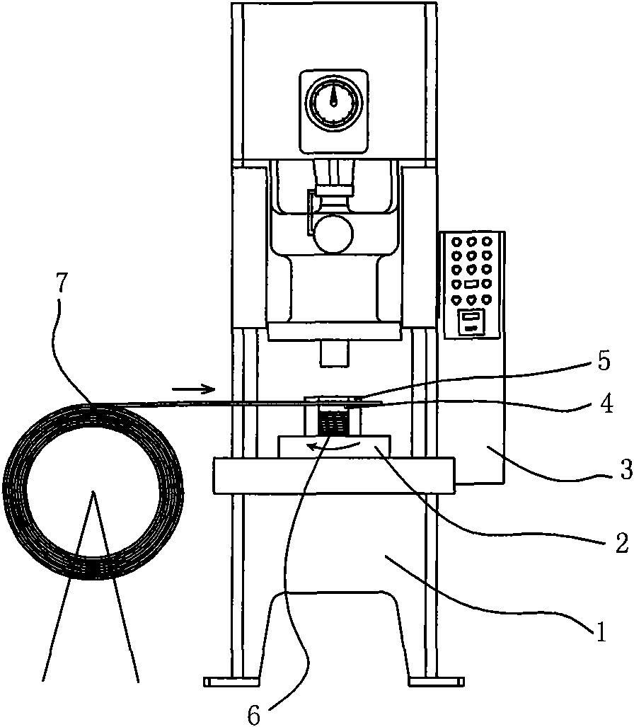
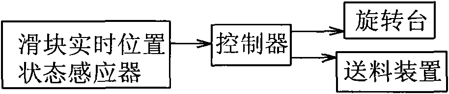
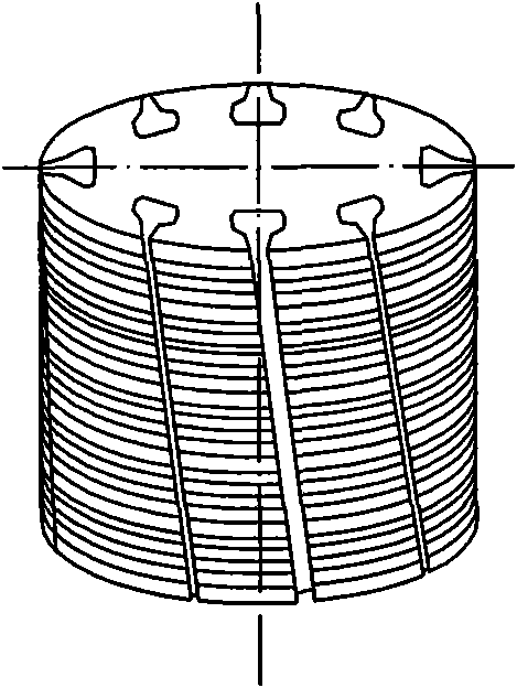
[0015] The present invention as figure 1 , 2 As shown, the strip steel is used as the raw material 7, and the punching machine 1 and the punching riveting die installed on the punching machine 1 are punched and riveted to form the stator and rotor piece by piece, and the lower die 5 of the punching die is punched out. A riveting bin 4 is provided, and a rotating device 2 is provided on the riveting bin 4. The punching machine 1 is provided with a controller 3 and a real-time position status sensor of the slider. The real-time position status sensor of the slider and the rotating device 2 are connected to the controller 3. The controller 3 instructs the rotating device 2 to rotate by an angle α before the next stator rotor segment 6 contacts the upper stator rotor segment 6 in the riveting chamber 4, so as to deflect between two stacked adjacent stator rotor segments 6 .

[0016] In order to overcome the problem of the thickness error of the strip steel 7, the rotation amount...


PUM


Abstract

The invention relates to a method for manufacturing laminated rotor and stator. In the method, strip steel is used as a raw material, and is punched and riveted by adopting a punch and a punch molding and rivet mould arranged on the punch to manufacture the stator and rotor; a lower mould of the punch molding and rivet mould is provided with a rivet bin; the rivet bin is provided with a rotating device; the punch is provided with a controller and a slide real-time position state inductor; the slide real-time position state inductor and the rotating device are connected with the controller; the controller indicates the rotating device to rotate at an angle alpha before the next stator and rotor is contacted with last stator and rotor in the rivet bin, so that the rotating device can deflect between two laminated adjacent stator and rotor. By combining high-speed automatic production line implementation of motor stator and rotor punching, the product accuracy can be greatly improved, the materials can be saved, the consumption is reduced, and the social benefit is remarkable.

Description

technical field [0001] The invention relates to a processing method of a laminated stator and rotor, in particular to a processing method of a laminated stator and rotor with inclined grooves or V grooves. Background technique [0002] In order to reduce harmonics, thereby reducing noise and vibration when the motor is running. Many motor stators and rotors adopt a laminated structure. In order to further improve the heat dissipation effect of the stator and rotor during operation and reduce the weight of the whole machine, some grooves are set on the stator and rotor. With the advancement of technology, the form of the motor has increased. In order to better improve the energy efficiency of the motor, the designer has improved the structure of the above-mentioned grooves, such as setting them as oblique or V-shaped, so that the heat dissipation is more consistent when the motor is running. Aerodynamic requirements. Such as image 3 , 4 Shown are the skewed rotor and the...

Claims


Application Information

Patent Timeline
IPC IPC(8): H02K15/02
Inventor 尤爱香
Owner YANGZHOU FORGING MACHINE TOOL
Why Eureka
Try Eureka