Downlink message forwarding method and serving gateway (S-GW)
A message forwarding and service gateway technology, applied in network data management, electrical components, wireless communication, etc., can solve problems such as waste of resources, achieve the effects of avoiding waste of resources, reducing the number of forwarding times, and improving transmission efficiency
- Summary
- Abstract
- Description
- Claims
- Application Information
AI Technical Summary
Problems solved by technology
Method used
Image

Examples
Embodiment 1
[0053] In this embodiment, the target eNB and the source eNB belong to the same MME and S-GW, that is, this embodiment is S1 handover within the MME and S-GW.
[0054] Figure 4 It is a schematic diagram of the S-GW processing the data and signaling flow of the downlink message when performing S1 handover in this embodiment, as shown in Figure 4 As shown, in this embodiment, when S1 handover occurs, the handover signaling flow and image 3 Similar, the difference is that since the source MME is the same as the target MME, therefore, Figure 4 exist image 3 Message 2 and Message 5 are reduced on the basis of .
[0055] Figure 5 In this embodiment, after the source eNB sends a handover command message to the UE, the flow chart of data forwarding, such as Figure 5 As shown, the forwarding of data by the source eNB mainly includes the following steps:
[0056] Step 501, S1 handover occurs, and after the source eNB sends a handover command message, it starts forwarding me...
Embodiment 2
[0063] In this embodiment, the S1 handover within the MME and across the SGW is taken as an example for illustration.
[0064] Figure 6 It is a schematic diagram of the flow direction of data flow and signaling flow when performing S1 handover in this embodiment, as Figure 6 As shown, in this embodiment, the signaling flow and Figure 4 Basically the same, the data flow is from the source eNB to the source S-GW and then to the target S-GW, and finally reaches the target eNB.
[0065] Figure 7 In this embodiment, after the source eNB sends the handover command message to the UE, the flow chart of forwarding the data flow is as follows: Figure 7 As shown, in this embodiment, forwarding data by the source S-GW mainly includes the following steps:
[0066] Step 701, S1 handover occurs, and after the source eNB sends a handover command message, it starts to forward the message to the source S-GW through the backhaul tunnel between it and the source S-GW;
[0067] Step 702,...
Embodiment 3
[0073] In this embodiment, an S1 handover across MMEs and SGWs is taken as an example for illustration.
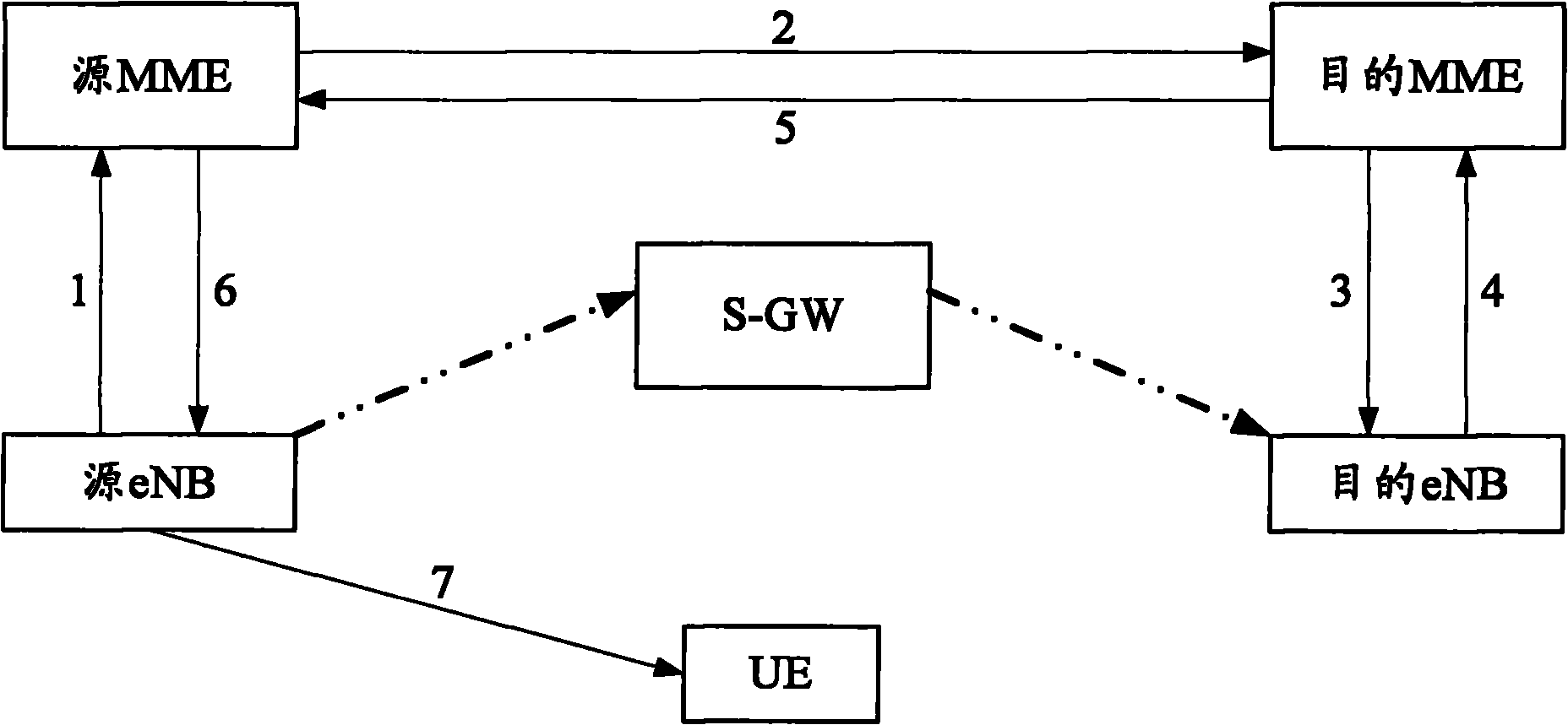
[0074] Figure 8 It is a schematic diagram of the flow direction of data flow and signaling flow when performing S1 handover in this embodiment, as Figure 8 As shown, in this embodiment, the signaling flow and image 3 Basically the same, the data flow is the same as Figure 6 resemblance.
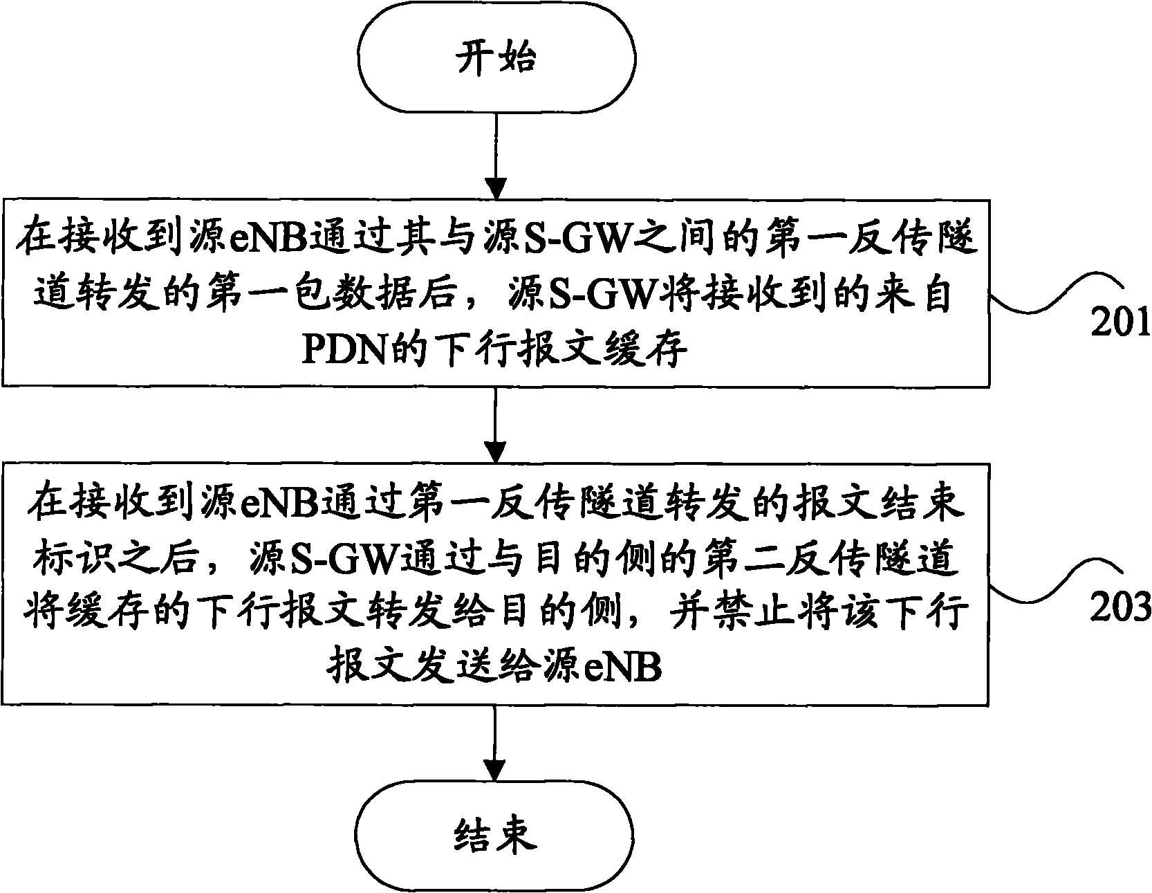
[0075] Figure 9 In this embodiment, after the source eNB sends the handover command message to the UE, the flow chart of forwarding the data flow is as follows: Figure 9 As shown, in this embodiment, forwarding data by the source S-GW mainly includes the following steps:
[0076] Step 901, S1 handover occurs, and after the source eNB sends a handover command message, it starts to forward the received message that needs to be sent to the UE to the source S-GW through the backhaul tunnel between it and the source S-GW;
[0077] Step 902, after receiving the forwarding message se...
PUM
 Abstract
Description
Claims
Application Information
 - Generate Ideas
- Intellectual Property
- Life Sciences
- Materials
- Tech Scout
- Unparalleled Data Quality
- Higher Quality Content
- 60% Fewer Hallucinations
Browse by: Latest US Patents, China's latest patents, Technical Efficacy Thesaurus, Application Domain, Technology Topic, Popular Technical Reports.
© 2025 PatSnap. All rights reserved.Legal|Privacy policy|Modern Slavery Act Transparency Statement|Sitemap|About US| Contact US: help@patsnap.com