Automatic hydraulic lock block

A locking block and hydraulic technology, applied in the direction of large fixed members, metal processing machinery parts, metal processing equipment, etc., can solve the problems of few clamping points, large volume, complex structure, etc., and achieve short clamping time and small volume , The effect of the overall structure is simple

Inactive Publication Date: 2011-01-05
ANYANG XINSHENG MACHINE TOOL
View PDF4 Cites 20 Cited by
  • Summary
  • Abstract
  • Description
  • Claims
  • Application Information

AI Technical Summary

Problems solved by technology

[0002] At present, most of the locking devices used in the feeding devices of inclined and vertical axes of various CNC machine tools in China are electromagnetic brakes or mechanical clamping devices. Electromagnetic brakes are mainly used to lock the rotary shaft. When the axis is a linear motor, it cannot be locked; mechanical clamping has a complex structure, large volume, few clamping points, uneven force, easy vibration during machining, loose clamping, manual operation, long changing time, and cannot To realize the automation of machine tools and components, the manufacturing cost is high; when the feed system of mechanical equipment is driven by a linear motor, it is required to have automatic clamping, fast, uniform, firm, simple structure, and small size. Electromagnetic brake or mechanical clamping device can not be achieved

Method used


Image

  • Automatic hydraulic lock block
  • Automatic hydraulic lock block
  • Automatic hydraulic lock block

Examples


Embodiment Construction

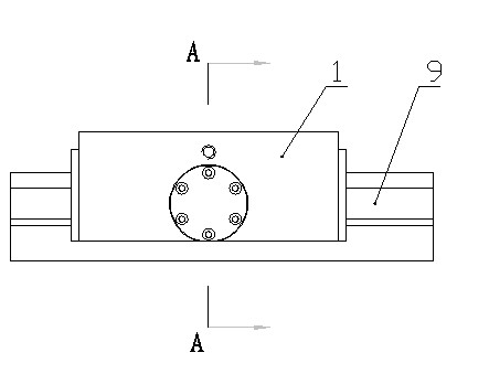
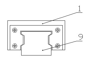
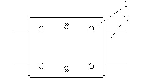
[0024] As shown in the figure, the automatic hydraulic locking block device of the present invention includes a locking block 1, and an oil cylinder guide hole is arranged on both sides of the locking block 1, and a piston rod 7 is put into the oil cylinder guide hole. 7 is provided with sealing ring 6 in the sealing groove, is formed sealing oil chamber by the oil cylinder guide hole of locking block 1, sealing ring 6, piston rod 7. A top tightening block 8 is provided at the thread of the piston rod 7, the disc spring 4 is put into the oil cylinder guide hole of the locking block 1, the gland 5 is fixed on the locking block 1, and the disc spring has a certain A joint 2 is provided on the side of the locking block 1.

[0025] The working principle of the present invention is as follows: the sealing ring 6 is put into the sealing groove of the piston rod 7, the piston rod 7 is put into the oil cylinder guide hole of the locking block 1, and the oil cylinder guide hole of the ...


PUM


Abstract

The invention relates to an automatic hydraulic lock block which comprises a lock block body, a piston rod, a disk spring, a seal ring, a press cover, a fixed screw, an oil joint, a puller block, a guide rail and the like. Hydraulic oil enters the lock block body from pipe joints on both sides of the lock block and then enters an oil cavity formed from the lock block body, the piston rod and the seal ring through an oil passage in the lock block body through electrical control, the piston rod is driven to move by means of oil pressure, the movement of the piston rod enables the disk spring to be compressed to drive the puller block to move, and thus, the purpose of loosing the guide rail by the lock block is realized. During shutdown power-off, because the hydraulic system stops supplying oil, the pressure of the oil cavity formed from the lock block body, the piston rod and the seal ring is reduced, the disk spring supports against the piston rod tightly due to the action of spring force, the piston rod drives the puller block to move, and thus, the purpose of locking the guide rail is realized.

Description

technical field [0001] The patent of the present invention is an automatic hydraulic locking block device, which can be installed on the feeding devices of various CNC machine tools and special machine tools, and is used to lock the linear guide rail of the feeding shaft when the power is off and the machine is stopped. It can prevent the feeding device from sliding down, and especially can meet the requirement of power-off brake locking when the feeding device is driven by a linear motor. Background technique [0002] At present, most of the locking devices used in the feeding devices of inclined and vertical axes of various CNC machine tools in China are electromagnetic brakes or mechanical clamping devices. Electromagnetic brakes are mainly used to lock the rotary shaft. When the shaft is a linear motor, it cannot be locked; mechanical clamping has a complex structure, large volume, few clamping points, uneven force, easy vibration during machining, loose clamping, manual...

Claims


Application Information

Patent Timeline
Patent Type & Authority Applications(China)
IPC IPC(8): B23Q1/26
Inventor 蒋清郝利军魏福贵苏春堂王安民郭章信吕德领吕乐韩向阳李根夏斌徐再云白家放李明涛王焱陆广
Owner ANYANG XINSHENG MACHINE TOOL
Why Eureka
Try Eureka