Fiber grating composite insulator and manufacturing method thereof

A composite insulator and fiber grating technology, which is applied in the direction of insulators, clad optical fibers, optical waveguides, etc., can solve the problems of low mechanical properties, low manufacturing efficiency, and susceptibility to environmental corrosion, and achieve high monitoring accuracy and improved accuracy , the effect of precise transmission

Active Publication Date: 2011-01-05
CENT CHINA GRID +2
View PDF6 Cites 10 Cited by
  • Summary
  • Abstract
  • Description
  • Claims
  • Application Information

AI Technical Summary

Problems solved by technology

[0004] The purpose of the present invention is to overcome the defects and problems existing in the prior art that affect the transmission of light sensing signals, be susceptible to environmental corrosion, low mechanical properties, and low manufacturing efficiency, and provide a method that accurately transmits light sensing signals, is not easy to Fiber Bragg Grating Composite Insulator Affected by Environmental Corrosion, Good Mechanical Properties, and High Manufacturing Efficiency and Manufacturing Method

Method used


Image

  • Fiber grating composite insulator and manufacturing method thereof
  • Fiber grating composite insulator and manufacturing method thereof
  • Fiber grating composite insulator and manufacturing method thereof

Examples


Embodiment

[0076] A method for manufacturing the above-mentioned fiber grating composite insulator, the method for manufacturing includes the following steps in sequence:

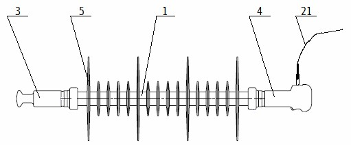
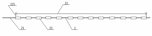
[0077] Step 1: first divide the optical fiber 2 into a grating coverage area 22 and a pigtail 21, and then evenly arrange 13 gratings 23 on the optical fiber 2 located in the grating coverage area 22, and the length of the pigtail 21 is greater than or equal to 500mm;

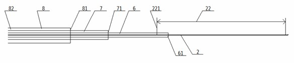
[0078] The second step: firstly put the white sleeve 6 on the optical fiber 2, and the inside of the white sleeve 6 is equipped with a pigtail 21 and a grating 23 in the grating coverage area 22, between the head 61 of the white sleeve and the tail 221 of the grating coverage area The distance between them is 150mm, and a metal hose 7 with a diameter of 1.5mm is placed on the outside of the white casing 6, and the distance between the tail 221 of the grating coverage area and the head 71 of the metal hose is 5mm, and then the metal hose A hollow steel ...


PUM

PropertyMeasurementUnit
lengthaaaaaaaaaa
lengthaaaaaaaaaa
distanceaaaaaaaaaa

Abstract

The invention relates to a fiber grating composite insulator comprising a core rod, a high-voltage end fitting and a low-voltage end fitting, wherein the high-voltage end fitting and the low-voltage end fitting are arranged on both ends of the core rod; the center of the core rod is provided with a fiber; the fiber comprises a grating coverage area and a tail fiber, wherein a grating coverage area is internally and uniformly provided with 3-20 gratings, and the length of the tail fiber is longer than or equal to 500mm; and the fiber is sequentially sleeved with a white sleeve, a metal hose and a hollow steel tube from inside to outside. A manufacturing method of the fiber grating composite insulator comprises the following steps of: firstly manufacturing the fiber; then packaging the fiber; then drawing the packaged fiber and soaked glass fibers out of a mould together to manufacture the core rod; then sawing the hollow steel tube to strip to expose the tail fiber; and then sequentially carrying out fitting pre-crimping, graded injection molding and secondary crimping to obtain the needed fiber grating composite insulator. The invention can not only realize the on-line monitoring of the mechanical property and the electric property of the fiber grating composite insulator and have difficult environmental corrosion and better mechanical property, but also accurately transmit the optimal sensing signals, save the production cost and enhance the manufacturing efficiency.

Description

technical field [0001] The invention relates to a composite insulator, in particular to an optical fiber grating composite insulator and a manufacturing method thereof, and is particularly applicable to an optical fiber grating composite insulator above 500KV and its manufacture. Background technique [0002] The performance of high-voltage insulators, especially the mechanical and insulating properties, has a very important impact on the safe operation of the power system, so the mechanical and insulating properties of insulators must be monitored regularly. The traditional monitoring method of composite insulators is based on the requirements of DL / T864-2004, inspections are carried out every 1-2 months, and insulators are taken from the tower and sent to the laboratory for performance inspection every 3-5 years. However, this sampling inspection method has disadvantages such as high work intensity, high risk of climbing poles, and long time consumption. Not only the whole...

Claims


Application Information

Patent Timeline
Patent Type & Authority Applications(China)
IPC IPC(8): H01B17/00H01B17/38H01B19/00G01R31/00G02B6/02
Inventor 陈继东王家礼吴伯华刘溟史天如张予杨同友杨帆马剑辉祝翔胡学秋范欣来熊鹏王晓楠杨红军
Owner CENT CHINA GRID
Why Eureka
Try Eureka