
Work duplex-head grinding apparatus, and work duplex-head grinding method

A technology of double-sided grinding and workpiece, applied in the field of double-sided grinding device of workpiece and double-sided grinding of workpiece, can solve the problems of large deviation, exceeding 0.2μm, etc., and achieve the effect of small deviation

Active Publication Date: 2011-01-05
SHIN-ETSU HANDOTAI CO LTD
View PDF1 Cites 18 Cited by
  • Summary
  • Abstract
  • Description
  • Claims
  • Application Information

AI Technical Summary

Problems solved by technology

[0017] However, for a chip that has been double-sided ground using such a conventional double-side grinding device or double-side grinding method, if the approximate nano-topography is measured, the deviation is large, and the wavelength of the nano-topography is as small as 10 mm. Possibly more than 0.2μm

Method used


Image

  • Work duplex-head grinding apparatus, and work duplex-head grinding method
  • Work duplex-head grinding apparatus, and work duplex-head grinding method
  • Work duplex-head grinding apparatus, and work duplex-head grinding method

Examples


Embodiment 1

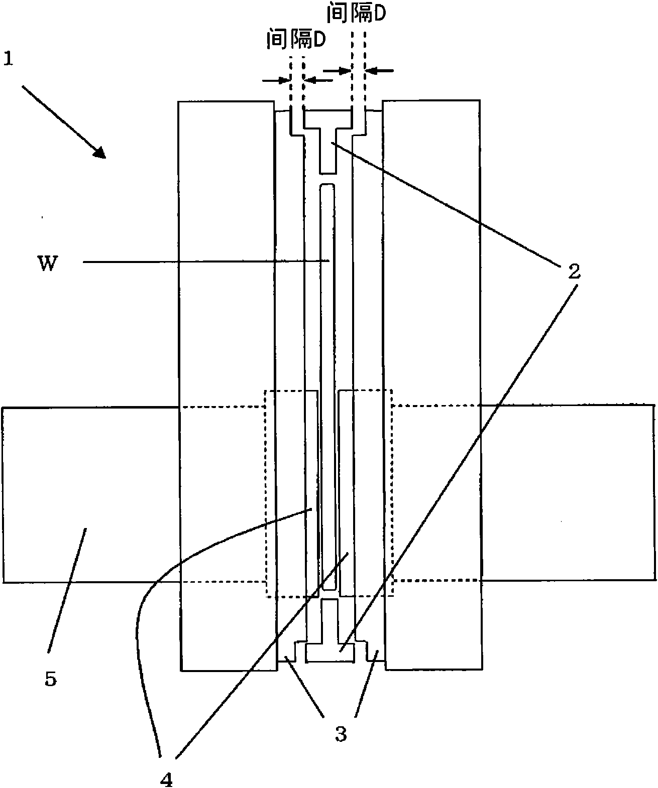
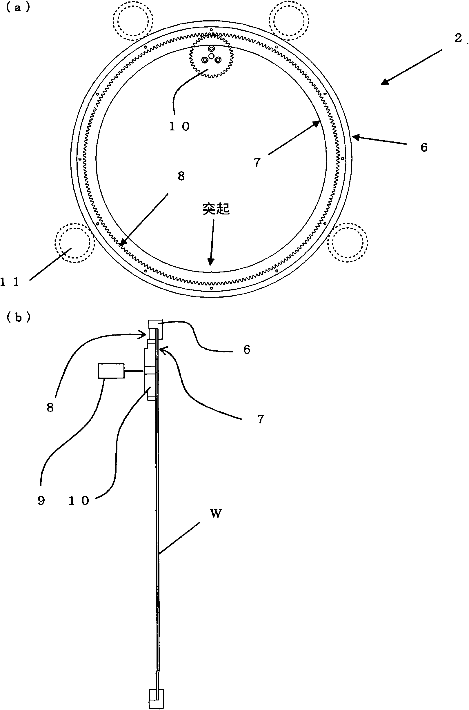
[0107] use figure 1 The double-sided grinding device 1 for workpieces of the present invention shown in , performs double-sided grinding of workpieces (silicon chips with a diameter of 300 mm) according to the double-sided grinding method of the present invention.

[0108] The ring portion of the workpiece holder is made of alumina ceramics. The flatness of the workpiece holder was 5 μm, the parallelism was 5 μm, and the flatness of the hydrostatic support member was 15 μm.

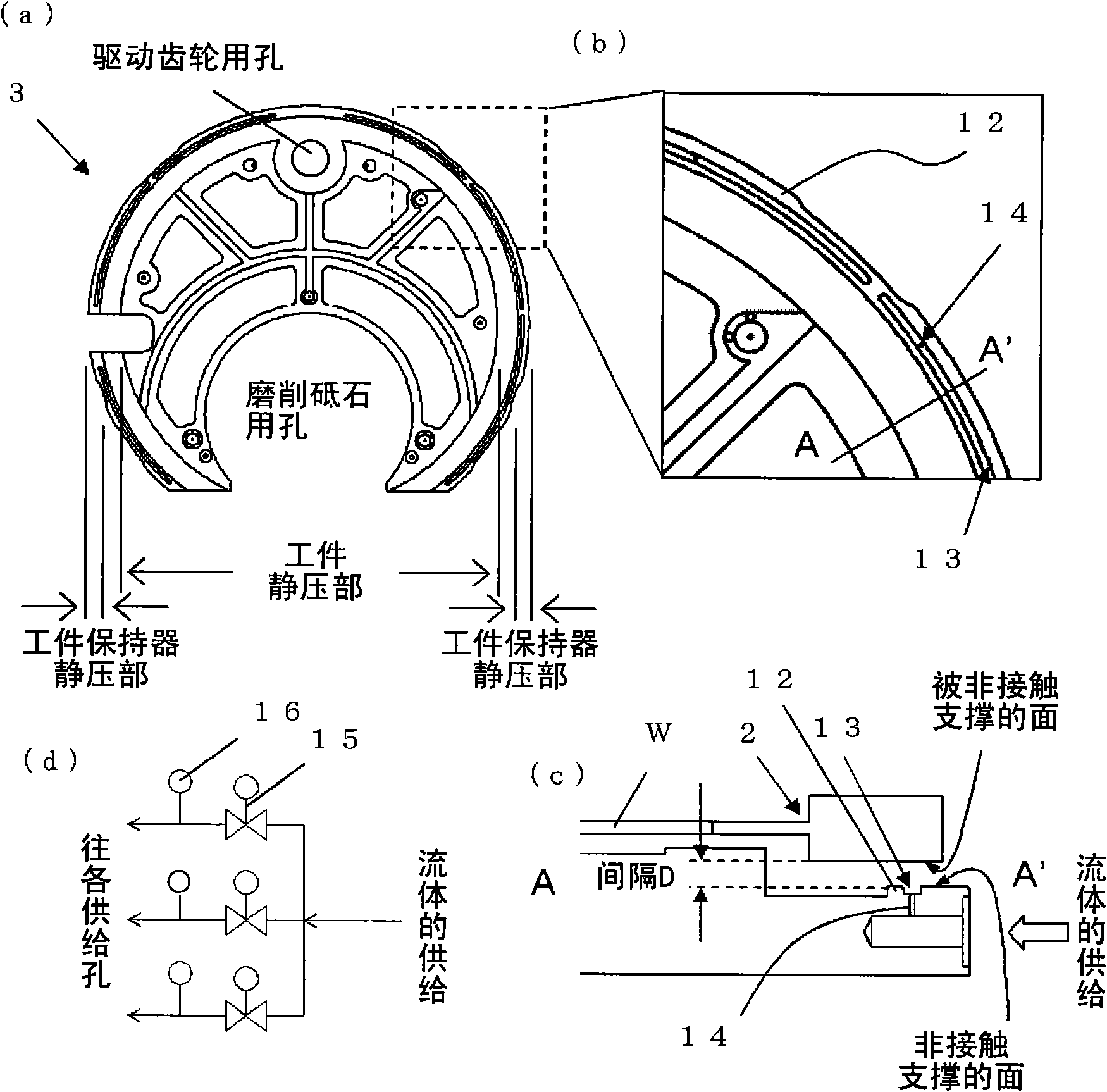
[0109] The distance between the workpiece holder and the static pressure support member was set to 30 μm. In addition, water was supplied from the supply hole of the static pressure support member, and the workpiece holder was supported non-contact by a static pressure of 0.6 MPa. Furthermore, SD#3000 whetstone and SD#8000 whetstone (vitrified sintered whetstone manufactured by Japan United Materials Co., Ltd. (A.L.M.T)) composed of diamond grains with an average particle size of 1 μm or less and vitri...

Embodiment 2

[0117] (Example 2, Comparative Example 2)

[0118] A workpiece (a silicon chip with a diameter of 300 mm) was ground in the same manner as in Example 1, except that SD#8000 whetstone was used as the whetstone, and the setting of the static pressure value by water was changed.

[0119] The static pressure generated by water was 0.3Mpa, 0.8Mpa, 1.0MPa (the above is Example 2), and 0.2MPa (Comparative Example 2).

[0120] Figure 7 Indicates the result based on the static pressure value generated by water and the approximate nano-morphology of the ground workpiece. In addition, the value of the approximate nanomorphology of Example 1 is also shown as a reference (value in hydrostatic pressure 0.6 Mpa).

[0121] In Comparative Example 2, the approximate nano-topography is as large as 0.8 μm, and in Example 2, all are suppressed below 0.2 μm.

[0122] In this way, if the static pressure value is smaller than 0.3 MPa, the approximate nano-morphology becomes remarkably large, and ...


PUM


Abstract

Provided is a work duplex-head grinding apparatus comprising an autorotation work holder for supporting a thin-plate work along the radial direction from the outer circumference side, a pair of static-pressure supporting members positioned on the two sides of the work holder, for supporting the work holder in a non-contact manner from the two sides along the axial direction of autorotation by the static pressure of a fluid, and a pair of grinding stones for grinding simultaneously the two faces of the work supported by the work holder. In the work duplex-head grinding apparatus, the spacing between the work holder and the static-pressure supporting members is 50 [mu]m or less, and the static-pressure supporting members support the work holder at the fluid static-pressure of 0.3 MPa or higher. Thus, there are provided the work duplex-head grinding apparatus and a duplex-head grinding method, in which the work duplex-head grinding operation can stabilize such a position taken along the axial direction of the autorotation of the work holder supporting the work from the outer circumference side, as might otherwise deteriorate the nano-topography of the work.

Description

technical field [0001] The present invention relates to a double-sided grinding device for workpieces and a double-sided grinding method for workpieces, which are used to simultaneously grind both sides of thin plate-shaped workpieces such as silicon chips; A double-sided grinding device for grinding both sides of a workpiece by a workpiece holder supporting a workpiece, and a double-sided grinding method for a workpiece. Background technique [0002] In advanced devices using large-diameter silicon chips such as 300 mm in diameter, the size of surface relief components called nanotopography (nanotopography) in recent years will become a problem. Nano-topography is a kind of surface shape of the chip. Its wavelength is shorter than that of bending and warping, and its wavelength is longer than that of surface roughness. Extremely shallow undulating composition. The nano-topography is considered to affect the yield of the shallow trench isolation (STI) process in the compon...

Claims


Application Information

Patent Timeline
Patent Type & Authority Applications(China)
IPC IPC(8): B24B7/17B24B41/06B24D3/00B24D3/14H01L21/304
CPCB24B37/28B24B41/067
Inventor 加藤忠弘小林健司
Owner SHIN-ETSU HANDOTAI CO LTD
Learn More