Manufacturing method of panel-type heat pipe
The invention relates to a technology of a flat-plate heat pipe and a manufacturing method, which are applied in the field of heat pipe manufacturing, and can solve the problems of large thermal resistance and poor heat dissipation performance of the flat-plate heat pipe, and achieve the effects of small thermal resistance and good heat transfer performance.
- Summary
- Abstract
- Description
- Claims
- Application Information
AI Technical Summary
Problems solved by technology
Method used
Image

Examples
Embodiment Construction
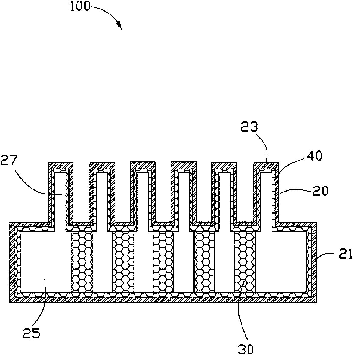
[0023] Figure 1 to Figure 3 Shown is a flat heat pipe 100 according to a first embodiment of the present invention. The flat heat pipe 100 is made by powder injection molding technology, and the specific steps are as follows:
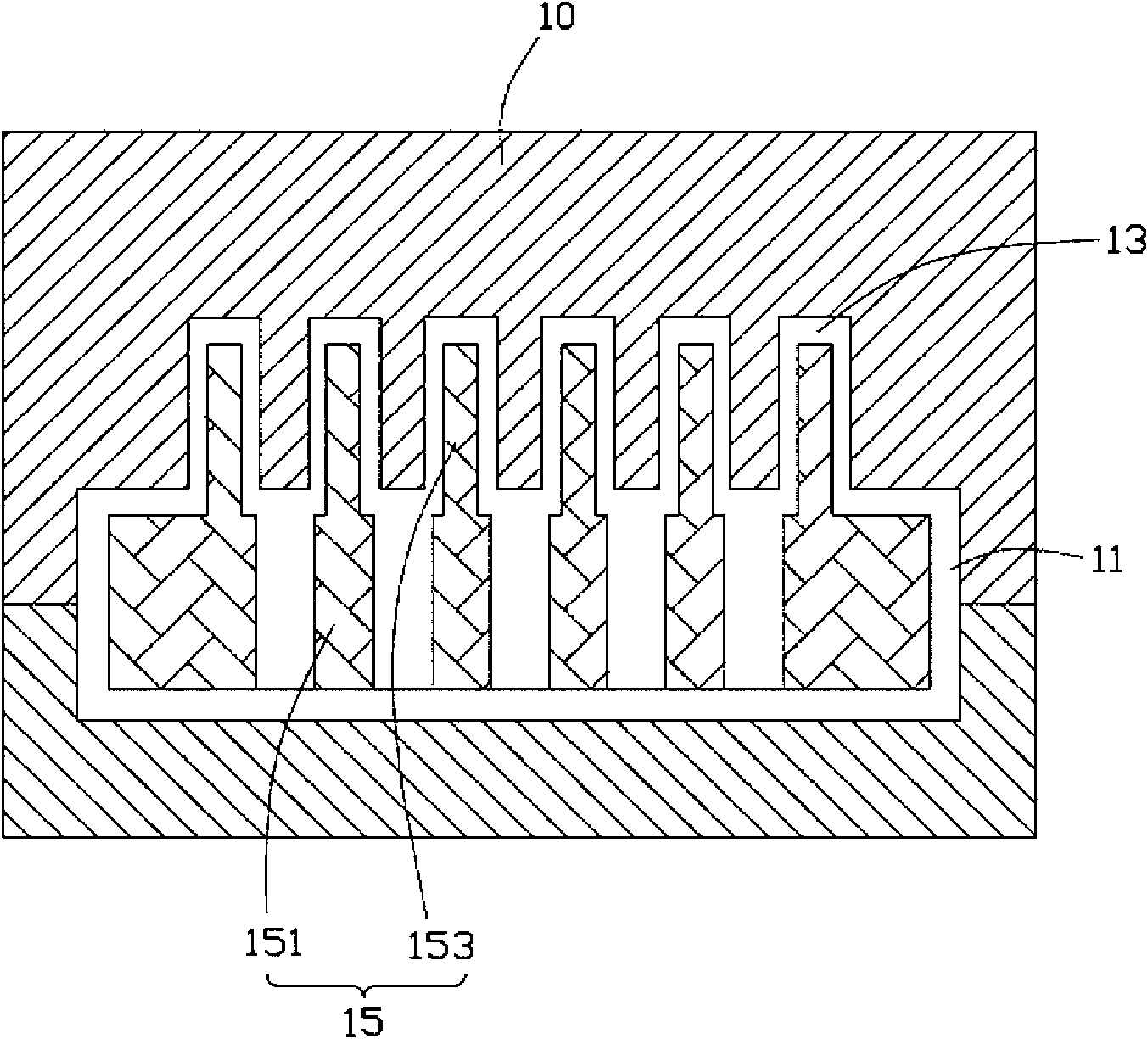
[0024] (1) A mold 10 is provided, and the mold 10 has a first cavity 11 and six second cavities 13 located in the upper middle of the first cavity 11 and communicating with it, arranged at equal intervals. The shape of the cavity jointly formed by the first and second mold cavities 11 and 13 is equivalent to the outer dimension of the flat heat pipe 100 . It can be understood that the shapes of the first cavity 11 and the second cavity 13 can be cuboid, cylinder or other geometric shapes, and in this embodiment, they are all cuboid.
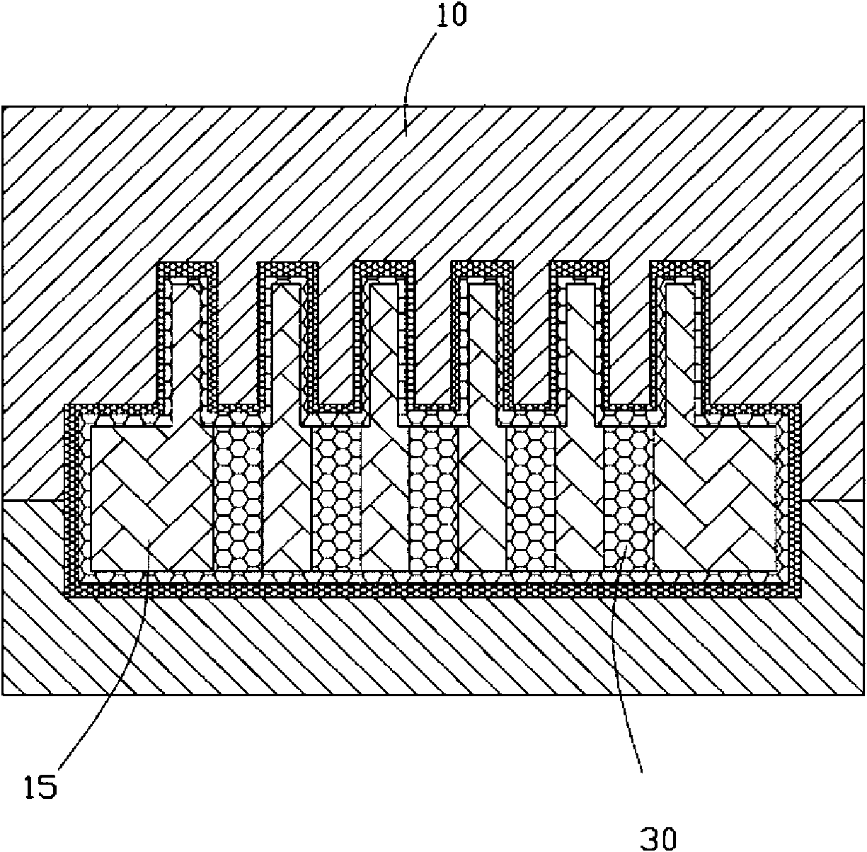
[0025] (2) A two-color molding injection machine (not shown in the figure) is provided, and the two-color molding injection machine has two injection systems in independent directions.
[0026] (3) Provide a first meta...
PUM
 Abstract
Description
Claims
Application Information