Check patentability & draft patents in minutes with Patsnap Eureka AI!

Backlight module

A technology for backlight modules and light source components, applied in optics, light guides, light sources, etc., can solve the problems of shortened service life, damage, and poor heat dissipation of light emitting diodes, so as to improve the brightness of light output and prevent warping and deformation. Effect

Inactive Publication Date: 2011-01-12
CORETRONIC
View PDF0 Cites 27 Cited by
  • Summary
  • Abstract
  • Description
  • Claims
  • Application Information

AI Technical Summary

Problems solved by technology

However, the elastic device directly pushing against the LED may cause poor heat dissipation of the LED, so that the service life of the LED is shortened or even damaged due to overheating

Method used


Image

  • Backlight module
  • Backlight module
  • Backlight module

Examples


Embodiment Construction

[0061] The aforementioned and other technical contents, features and effects of the present invention will be clearly presented in the following detailed description of a preferred embodiment with reference to the drawings. The directional terms mentioned in the following embodiments, such as: up, down, left, right, front or back, etc., are only directions referring to the attached drawings. Accordingly, the directional terms are used to illustrate and not to limit the invention.

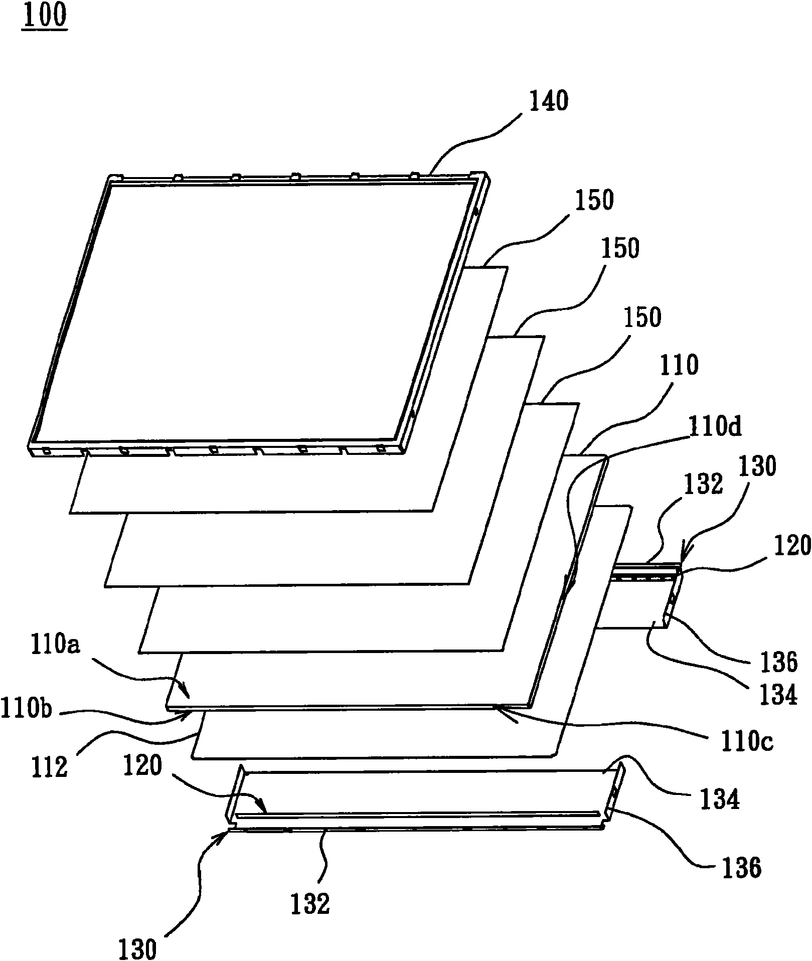
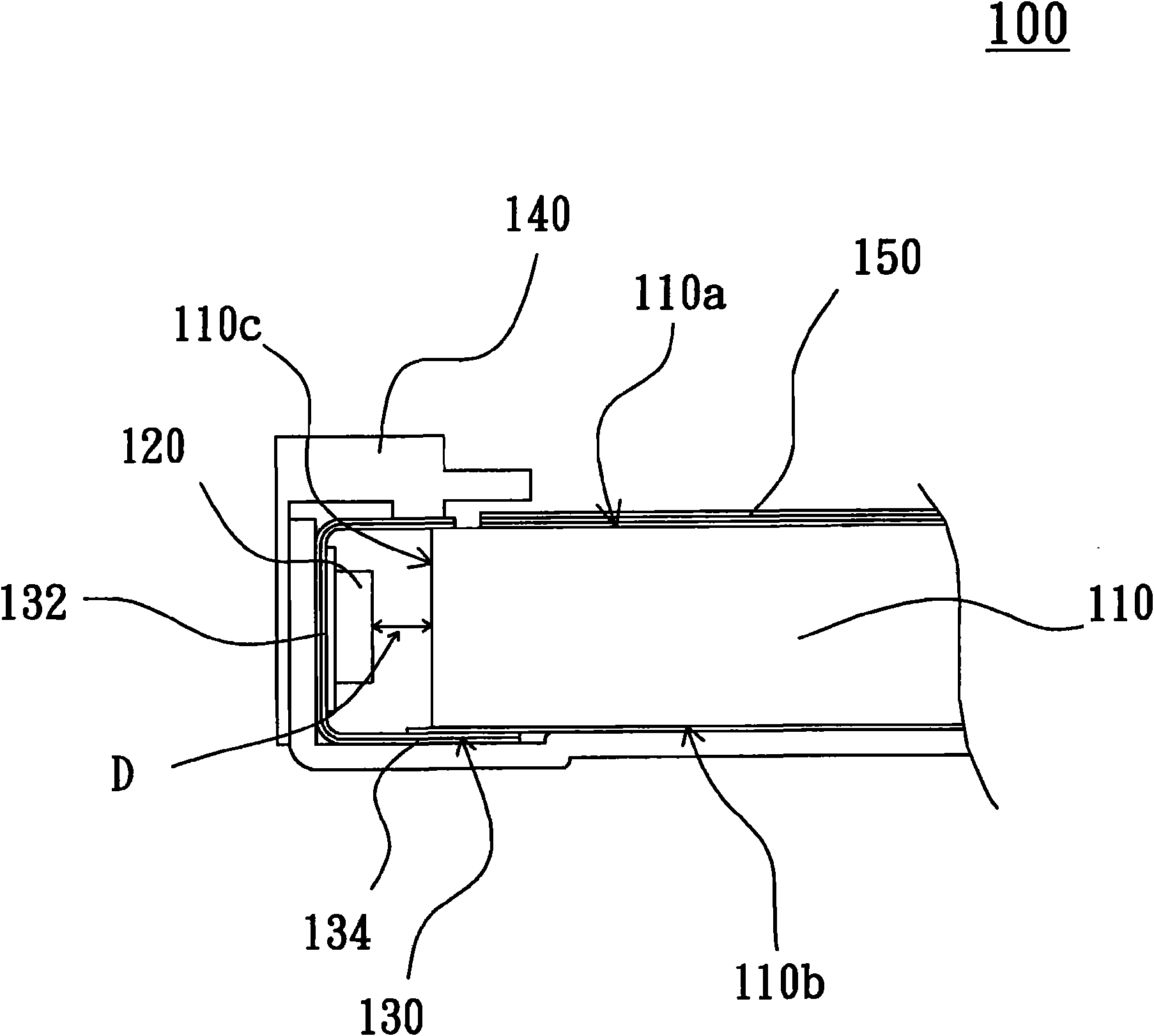
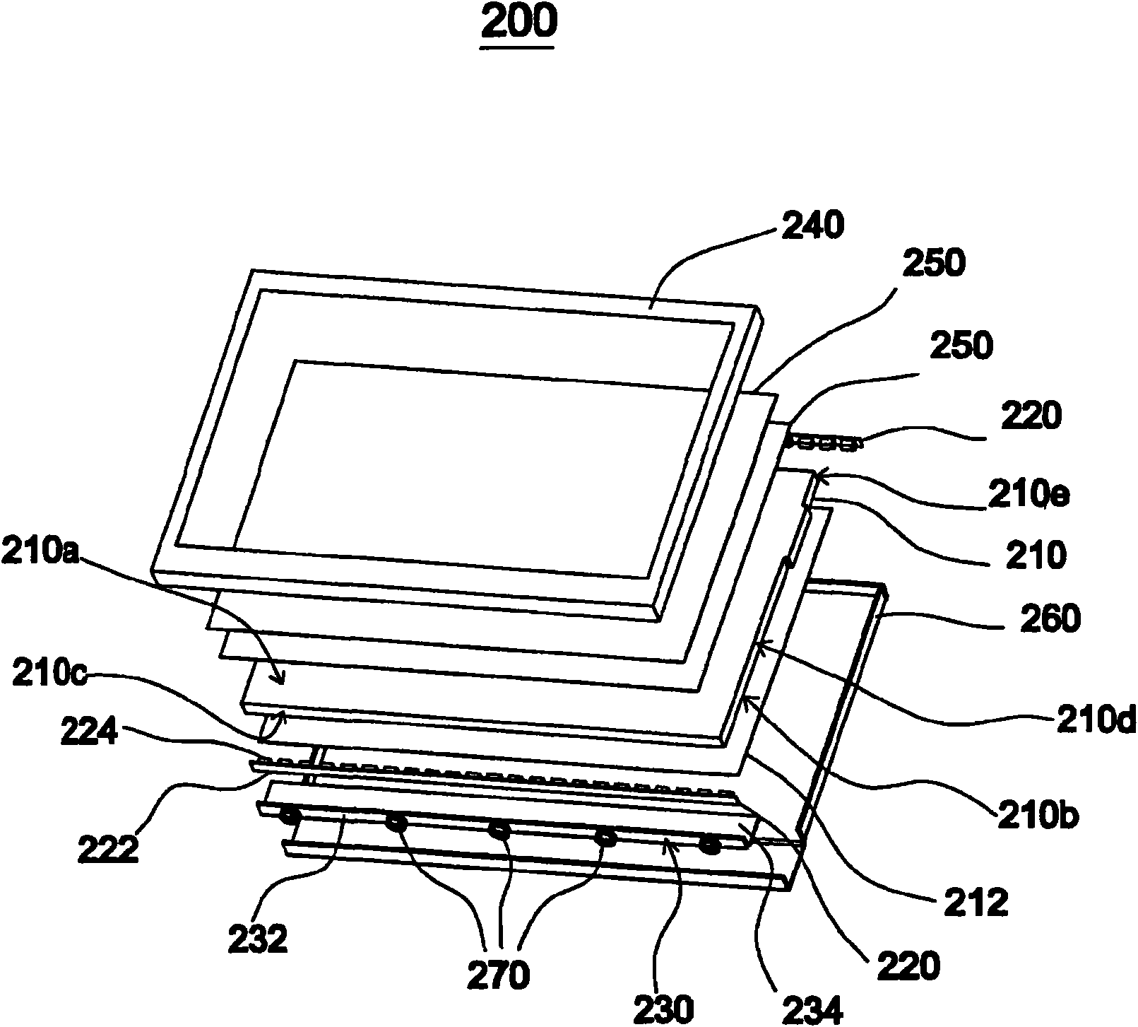
[0062] Figure 2A It is an exploded view of a backlight module according to the first embodiment of the present invention, Figure 2B It is a partially enlarged schematic diagram of the backlight module of the first embodiment of the present invention, Figure 2C is a top view of the backlight module of the first embodiment of the present invention, Figure 2D for Figure 2C The cross-sectional view of the backlight module along the line A-A. Please also refer to Figure 2A , Figure 2B , F...


PUM


Abstract

The invention relates to a backlight module which comprises a back plate, a light guide plate, at least one light source assembly, at least one heat radiating plate and at least one elastic device, wherein the light guide plate is arranged on the back plate and provided with a light emergent face, a bottom face corresponding to the light emergent face and a first light incident face connected with the light emergent face and the bottom face; the light source assembly is adjacent to the first light incident face of the light guide plate and comprises a light bar, and the light bar is arranged on the heat radiating plate between the heat radiating plate and the light guide plate; and the elastic device is arranged between the heat radiating plate and the back plate. The backlight module can enable the light bar to be abutted against the light incident face of the light guide plate and can provides proper expansion space for the possible expansion of the light guide plate.

Description

【Technical field】 [0001] The present invention relates to a light source module, and in particular to a backlight module applied to a liquid crystal display (LCD) as a surface light source. 【Background technique】 [0002] The liquid crystal display mainly includes a liquid crystal panel and a backlight module, wherein the backlight module is a surface light source arranged behind the liquid crystal panel. According to different configurations of light source components, such as cold cathode ray tubes or light emitting diodes, backlight modules can be divided into direct-type backlight modules and edge-type backlight modules. In the edge-lit backlight module, the light source assembly is arranged on the side of the light guide plate, so that the light beam emitted by the light source assembly can enter from the side of the light guide plate, and then exit from the light-emitting surface of the light guide plate. [0003] Figure 1A It is an explosion diagram of an existing b...

Claims


Application Information

Patent Timeline
Patent Type & Authority Applications(China)
IPC IPC(8): F21S8/00F21V17/00F21V8/00F21V29/00F21V15/04G02F1/13357F21Y101/02F21V29/70F21V29/85
Inventor 冯华德翁林助
Owner CORETRONIC
Features
  • R&D
  • Intellectual Property
  • Life Sciences
  • Materials
  • Tech Scout
  • Unparalleled Data Quality
  • Higher Quality Content
  • 60% Fewer Hallucinations
Learn More