Charge pump

A charge pump and circuit technology, applied in the direction of electrical components, adjusting electric variables, automatic power control, etc., can solve the problems of chip circuits not working normally, not applicable to constant power, and not using transient power consumption, etc.

Active Publication Date: 2012-11-07
SHANGHAI HUAHONG GRACE SEMICON MFG CORP
View PDF0 Cites 2 Cited by
  • Summary
  • Abstract
  • Description
  • Claims
  • Application Information

AI Technical Summary

Problems solved by technology

The current consumed by the charge pump when it starts up is mainly related to the clock frequency, the number of stages and the capacitance of each stage of the m-stage booster circuit. In the start-up phase, since there is no charge on the capacitors of each stage of the m-stage booster circuit, it is necessary to All capacitors are charged, so the starting current will be large
[0003] In modern industry, more and more charge pumps are used in radio frequency cards. The energy of radio frequency cards is obtained through inductive coupling, power (P) = current (I) * power supply voltage (VDD), because P is constant , if I is too large, VDD will inevitably decrease, causing other circuits in the chip to not work normally
Because the traditional charge pump will generate a large current during the start-up phase, it cannot be used on some platforms that have strict requirements on transient power consumption. It is only suitable for platforms with constant VDD, not for platforms with constant power.

Method used


Image

  • Charge pump
  • Charge pump

Examples


Embodiment Construction

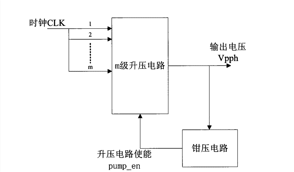
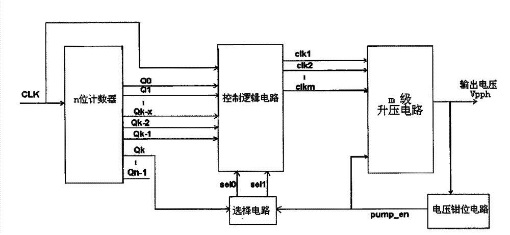
[0014] An embodiment of the charge pump of the present invention is as figure 2 As shown, it includes an m-level boost circuit and a voltage clamping circuit, the output voltage Vpph of the m-level boost circuit is output as a charge pump, and the voltage clamp circuit is connected to the output voltage of the m-level boost circuit Vpph, the output boost circuit enable signal pump_en is connected to the enable terminal of the m-level boost circuit, when the output voltage Vpph is higher than the clamped high voltage of the voltage clamp circuit, the boost circuit is enabled The signal pump_en controls to turn off the m-level booster circuit, and when the output voltage Vpph drops below the low clamp voltage of the voltage clamping circuit, the m-level booster circuit enabling signal pump_en controls the m-level booster circuit to be turned off. The stage booster circuit starts again, so that a stable output voltage Vpph is maintained circularly; it also includes a control log...


PUM


Abstract

The invention discloses a charge pump, wherein all levels of clock signal output ends of a multilevel booster circuit are connected with different frequencies of clock signals, a control logic circuit is used to adjust the frequency of each level of clock signals of the booster circuit according to the change of control signals; when the charge pump starts, the frequency of the booster circuit clock signals which are connected with all the levels of the clock signal input ends is low and then is increased gradually; and when the output voltage of the charge pump reaches a high clamp voltage, each level of booster circuit clock signals is set to have the same frequency of the original input clock CLK frequency. By using the charge pump of the invention, the starting current of the charge pump can be reduced and the ability of the charge pump can be ensured, thus the charge pump can be used in the occasion with the constant source power.

Description

technical field [0001] The invention belongs to the field of semiconductor integrated circuit design, in particular to a charge pump. Background technique [0002] Traditional charge pumps such as figure 1 As shown, it includes an m-level boost circuit and a voltage clamping circuit. The 1~m-level clocks of the m-level boost circuit use the same clock CLK, and the same clock CLK drives all stages of the m-level boost circuit to work, and the output voltage Vpph gradually rises. When the output voltage Vpph reaches the high clamp voltage of the voltage clamp circuit, that is, when the charge pump is started, the enable signal pump_en of the m-level boost circuit changes from high level to low level, thereby turning the The m-level booster circuit is turned off. When the output voltage Vpph drops below the clamping low voltage of the voltage clamping circuit due to leakage and other reasons, the m-level booster circuit enable signal pump_en changes from low level to high leve...

Claims


Application Information

Patent Timeline
Patent Type & Authority Patents(China)
IPC IPC(8): G05F3/08H03L7/00
Inventor 骆川
Owner SHANGHAI HUAHONG GRACE SEMICON MFG CORP
Why Eureka
Try Eureka