Switching appliance for AC circuit

A technology for switching electrical appliances and AC circuits. It is applied in the direction of electric switches, high-voltage/high-current switches, and circuits. It can solve the problems of easy jitter, slow opening and closing speeds, and low intelligence, and achieves novel and concise structures. The effect of low service life and manufacturing cost

Active Publication Date: 2014-06-04
JIANGSU MODERN POWER CAPACITOR
View PDF7 Cites 0 Cited by
  • Summary
  • Abstract
  • Description
  • Claims
  • Application Information

AI Technical Summary

Problems solved by technology

[0002] The existing medium and high voltage AC three-phase switchgear generally does not have intelligence, or the degree of intelligence is low, there is no precise guidance and control for the opening and closing of the switch dynamic and static contacts, and the opening and closing time points cannot be controlled on the phase of the AC waveform Set point, opening and closing speed at the same time is slow, it is prone to jitter when closing, and arcing phenomenon is easy to occur when breaking, and the functions of measurement, protection, signal, remote control, self-diagnosis and other functions are not or incomplete
This switching device cannot meet the needs of building a strong smart grid

Method used


Image

  • Switching appliance for AC circuit
  • Switching appliance for AC circuit

Examples


Embodiment 1

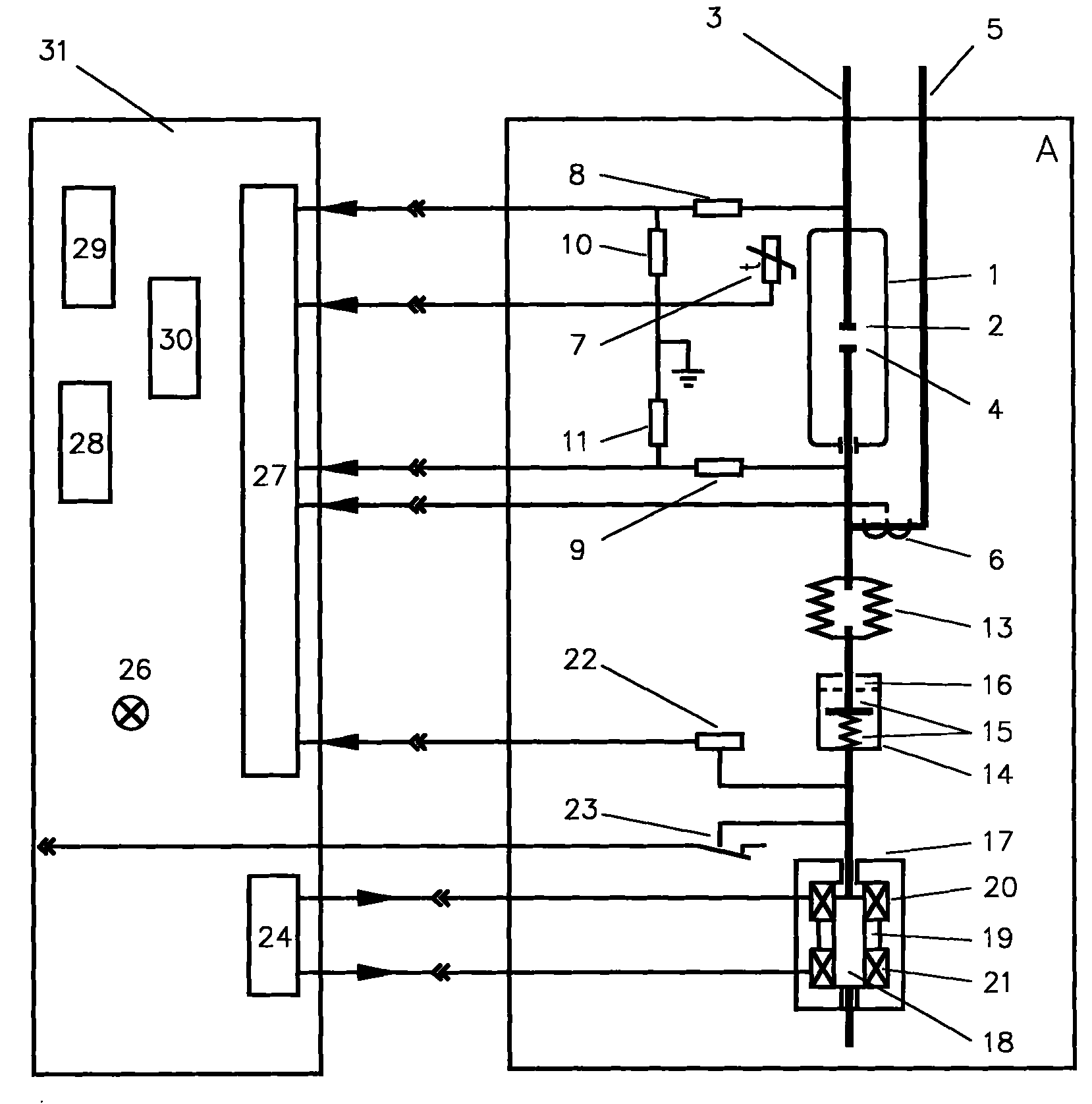
[0033] Such as figure 1 As shown, a switching device for an AC circuit of the present invention includes a switch, a switch driving device, a control unit 31 and a detection unit. Line 3, the moving contact 4 is connected to the moving contact lead-out line 5, the switch 1 can be a vacuum switching tube, the switch 1 is connected to the switch driving device through the insulator 13, the insulator 13 ensures that the switch 1 and the switch driving device are insulated from each other, and the switch drives The device includes a motion damping element 14 and a driving mechanism 17 , and the driving mechanism 17 is connected to the motion damping element 14 .

[0034] The control unit 31 includes a central processing unit 30 , a detection signal interface circuit 27 , a control interface circuit 24 , an input unit 29 and an output unit 28 . The control unit 31 controls the driving mechanism 17 through the control interface circuit 24 , and the driving mechanism 17 controls the...

Embodiment 2

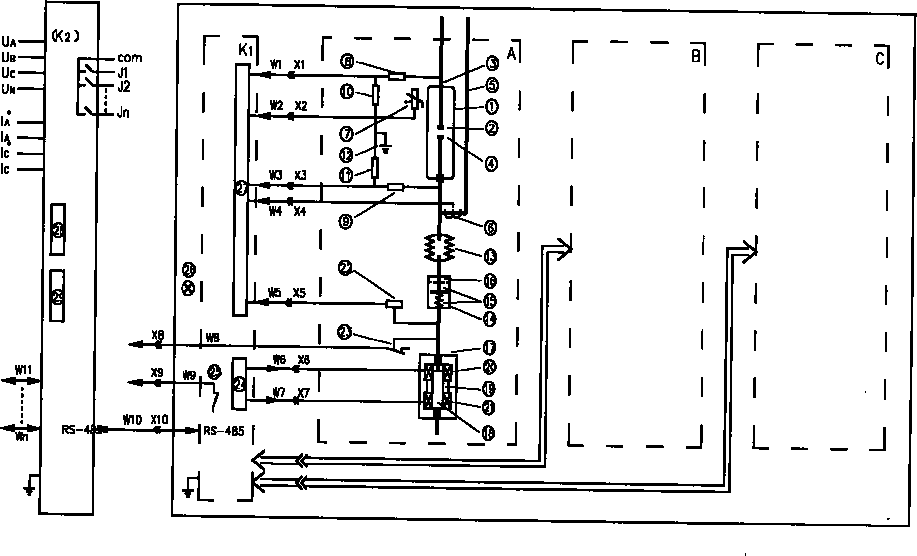
[0057] Such as figure 2 As shown, a switching device for an AC circuit includes three unipolar switches and a controller. The three unipolar switches are all connected to the controller, and at least two of the unipolar switches have the same structure, including vacuum switching tubes, insulation The component and the permanent magnet type split-on drive part, the vacuum switch tube, the insulating part and the permanent magnet type split-close drive part are connected in series.

[0058] A vacuum switching tube, an insulator, a permanent magnet opening and closing drive and a motion damping member that make up a unipolar switch are connected in series in a straight line; the permanent magnet opening and closing drive is bistable, That is, the switch is closed by the closing power supply, and the closing state remains after the closing power supply is removed. The switch is opened after being driven by the opening power supply, and the opening state is maintained after the o...


PUM


Abstract

The invention discloses a switching appliance for an AC circuit, which comprises a control unit, a detection unit, at least one switch and at least one switch driving device. The switch driving device is connected with the switch and is used for controlling the on and off of the switch; the detection unit is used for detecting a working state of the switch and / or the switch driving device; and the control unit controls the switch driving device according to a signal detected by the detection unit. That the switch is on at the contact zero-voltage moment and the switch is off at the contact zero-current moment is guaranteed, and despite of the on / off of the switch, the switch can avoid an arcing phenomenon. When the switch is on, jitter is not generated, the frequent operation of the switch is allowed and the switch cannot be damaged. Therefore, an accident caused by the switch is avoided, and the service life of the switch is prolonged. The switching appliance has the advantages of excellent performance, novel and simple structure, high reliability, high maintenance and low manufacturing cost.

Description

technical field [0001] The invention relates to a switching device, in particular to a switching device for an AC circuit. Background technique [0002] The existing medium and high voltage AC three-phase switchgear generally does not have intelligence, or the degree of intelligence is low, there is no precise guidance and control for the opening and closing of the switch dynamic and static contacts, and the opening and closing time points cannot be controlled on the phase of the AC waveform Set point, opening and closing speed at the same time is slow, it is prone to jitter when closing, and arcing phenomenon is easy to occur when breaking, and the functions of measurement, protection, signal, telecontrol, self-diagnosis and other functions are not or incomplete. This switching device cannot meet the needs of building a strong smart grid. Contents of the invention [0003] The technical problem to be solved by the present invention is to overcome the deficiencies of the ...

Claims


Application Information

Patent Timeline
Patent Type & Authority Patents(China)
IPC IPC(8): H01H9/56H01H3/28H01H33/66
Inventor 施博一宋玉锋顾明锋
Owner JIANGSU MODERN POWER CAPACITOR
Why Eureka
Try Eureka