Welding gun clamping device based on welding visual system

A vision system and a clamping device technology, which are applied to the device supporting electrode clamps, welding equipment, welding accessories, etc., can solve the problems such as the lens and camera cannot be well protected, difficult to operate, and the field of view is skewed and jittered. To achieve the effect of good monitoring effect, small adjustment amount and long service life

Active Publication Date: 2017-05-31
GUANGDONG FUWEIDE WELDING
View PDF8 Cites 10 Cited by
  • Summary
  • Abstract
  • Description
  • Claims
  • Application Information

AI Technical Summary

Problems solved by technology

The other end of the magic arm is fixed on the robot or mobile platform. Since the joints of the magic arm are fixed by bolts, and all joints are fixed by one bolt, it is difficult to operate; in addition, due to the flexible structure, it is difficult to operate on a welding robot or a welding platform. When moving, it is prone to shaking and loosening, which affects the shooting effect; finally, the magic arm can move in all directions, so it is very difficult to fix the camera in a suitable position, causing the field of view to be skewed and shaken. The camera is fixed on the crab claw, and the lens And the camera is not well protected
②At present, the welding torch clamping devices used by some scientific research institutions or companies are large and heavy, with complex structures and difficult adjustments. Usually, the camera is fixed at an exact position, and the object distance and camera angle are fixed and cannot be adjusted.
Therefore, when the camera model is changed or the lens is changed, the camera assembly is not suitable or the object distance changes, resulting in inaccurate focus and blurred images.
③The clamping device of the vision system is complex and made of cast iron, which is easily affected by electromagnetic interference, and the cost is high

Method used


Image

  • Welding gun clamping device based on welding visual system
  • Welding gun clamping device based on welding visual system
  • Welding gun clamping device based on welding visual system

Examples


Embodiment Construction

[0024] In order to make the object, technical solution and advantages of the present invention clearer, the present invention will be further described in detail below in conjunction with the embodiments and accompanying drawings.

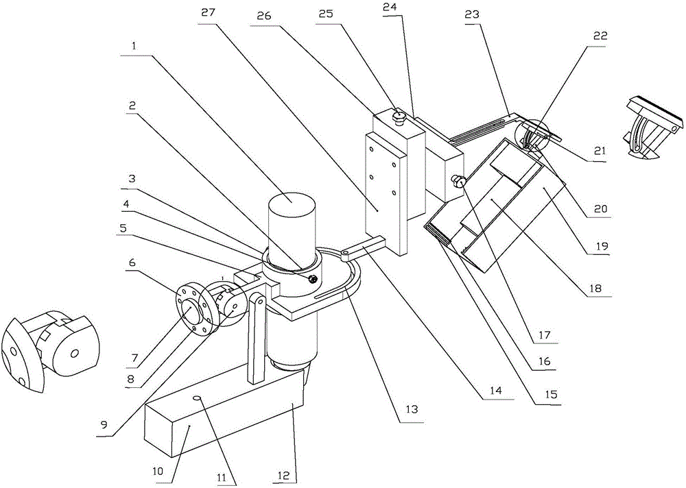
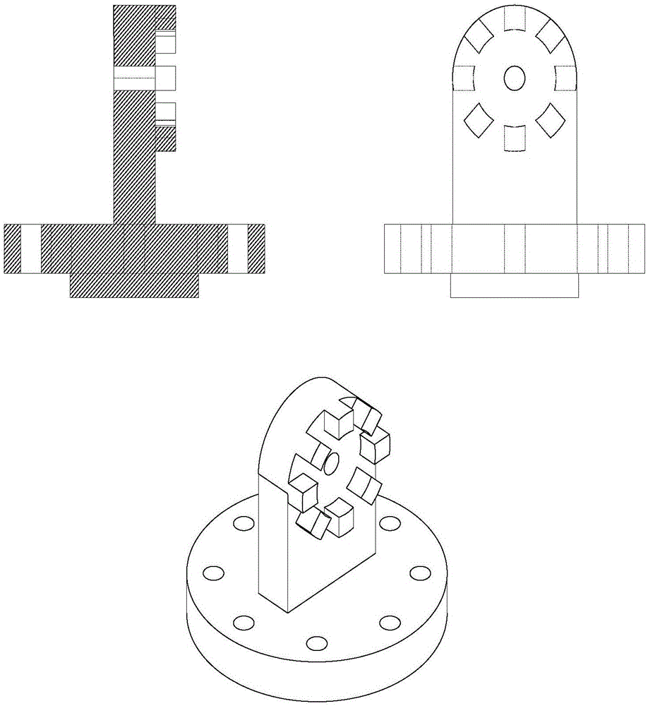
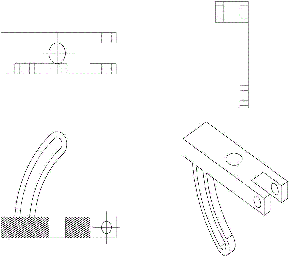
[0025] Such as figure 1 , figure 2 and image 3 Shown is the structure of the welding torch clamping device based on the welding vision system, including: welding torch 1, flange plate 6, cross slide mechanism, horizontal moving guide rail, camera box 19, coupling 8, nylon ring and welding torch outer cylinder;

[0026] The nylon ring and the outer barrel of the welding torch are sleeved on the outside of the welding torch, and the nylon ring 2 is used to wrap the welding torch;

[0027] The flange connection is provided with a bracket;

[0028] The coupling is used to connect the welding torch outer cylinder 3 and the bracket connected to the flange; the coupling can be disassembled, and the couplings are fastened with bolts 9, and the trapezo...


PUM


Abstract

The invention discloses a welding gun clamping device based on a welding visual system. The clamping device is used for welding of robot deep penetration welding and comprises a welding fun, a flange plate, a cross sliding table mechanism, a horizontal moving guide rail, a camera box, a coupling, a nylon ring and a welding gun outer barrel. The welding gun is sleeved with the nylon ring and the welding outer barrel. The nylon ring is used for wrapping the welding gun. A support is arranged on the flange plate in a connected mode. The coupling is used for connecting the welding gun outer barrel and the support connected to the flange plate. The welding gun outer barrel is circular, a support is arranged on the welding gun outer barrel in a connected mode, a reinforcing rib is arranged at the tail end of the support, a gas protection holding cover is connected to the lower portion of the support, and a U-shaped groove is formed in the edge of the welding gun outer barrel. The cross sliding table mechanism is fixed to the welding gun outer barrel through a connected U-shaped groove support. The horizontal moving guide rail is fixed to the cross sliding table mechanism. The camera box is mounted on the horizontal moving guide rail and moves horizontally on a horizontal sliding table through the horizontal moving guide rail.

Description

technical field [0001] The invention relates to the technical field of welding torch clamping devices, in particular to a welding torch clamping device applied to deep penetration welding of robots and based on a welding vision system. Background technique [0002] High-efficiency deep penetration TIG welding has the advantages of no groove opening in the welding process, single-sided penetration and double-sided forming, fast welding speed and high welding efficiency. However, during welding, the welding current is high, which usually produces strong arc light, which makes it difficult to observe the weld seam information during the welding process and affects the welding quality. In addition, a series of problems such as strong radiation endangering human health and excessive electromagnetic interference will occur. With the development of welding automation and intelligent technology, the application of machine vision system in the field of welding has become more and mor...

Claims


Application Information

Patent Timeline
Patent Type & Authority Applications(China)
IPC IPC(8): B23K9/28B23K9/167B23K9/127B23K9/32
CPCB23K9/127B23K9/167B23K9/287B23K9/32
Inventor 石永华顾盛勇崔延鑫
Owner GUANGDONG FUWEIDE WELDING
Why Eureka
Try Eureka