Eureka AIR delivers breakthrough ideas for toughest innovation challenges, trusted by R&D personnel around the world.

Switched reluctance motor with electromotion and power generation conversion function used for electric vehicle

A technology of switched reluctance motor and conversion function, which is applied to electric vehicles and controls the directions of generators and motors through magnetic field changes. High, convenient control and reliable performance

Inactive Publication Date: 2011-01-12
谢庆生
View PDF2 Cites 11 Cited by
  • Summary
  • Abstract
  • Description
  • Claims
  • Application Information

AI Technical Summary

Problems solved by technology

[0002] At present, the electric vehicle motors on the domestic market are almost all permanent magnet motors, and the switched reluctance motors with high performance are still used very little; although the permanent magnet motor itself has a certain power generation function, it is directly affected by the reaction force. Conversely, when generating electricity, its own structure and the structure and principle of the generator are quite different, so its power generation efficiency is very low, and it has almost no use value.

Method used


Image

  • Switched reluctance motor with electromotion and power generation conversion function used for electric vehicle
  • Switched reluctance motor with electromotion and power generation conversion function used for electric vehicle
  • Switched reluctance motor with electromotion and power generation conversion function used for electric vehicle

Examples


Embodiment Construction

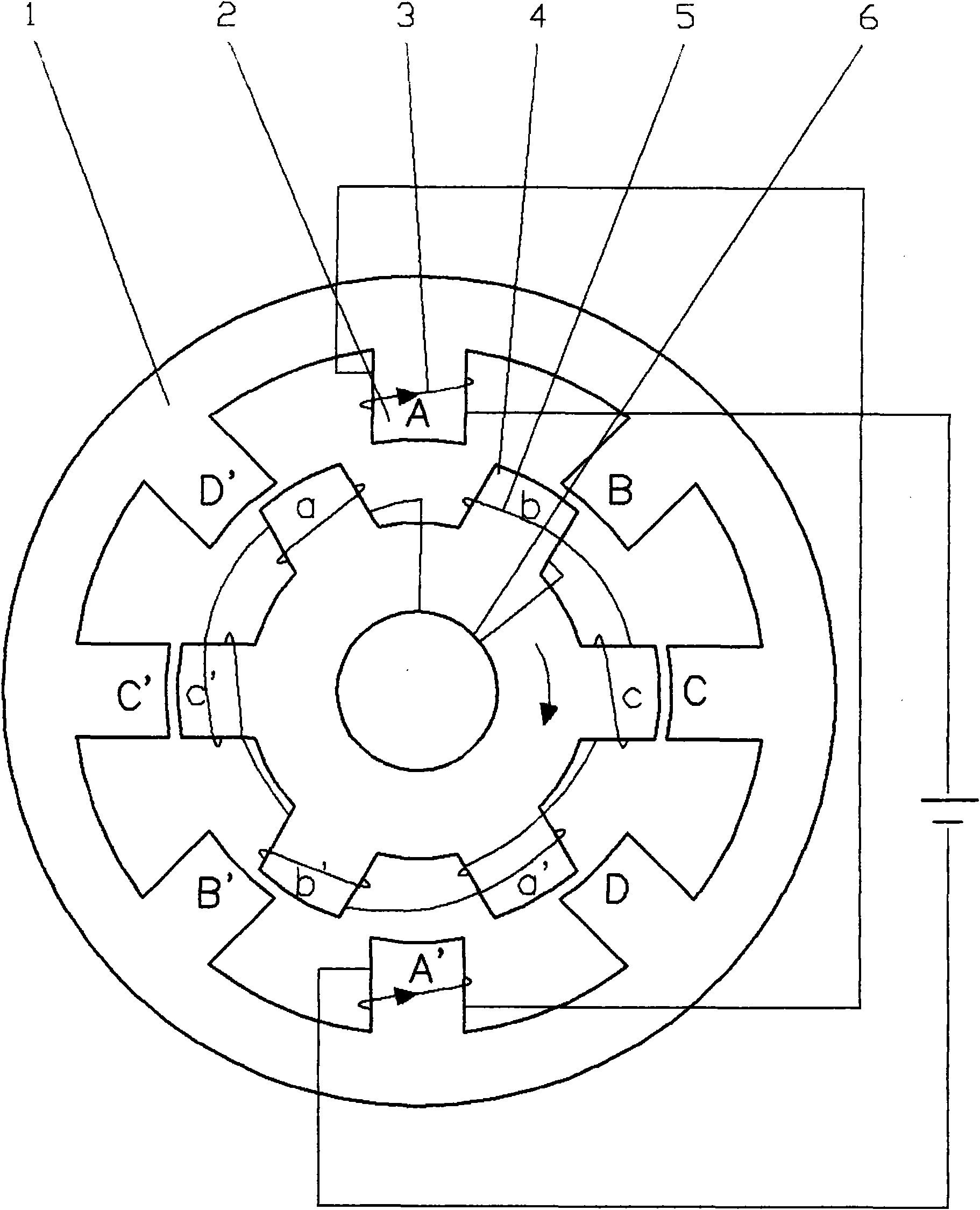
[0016] Please see attached figure 1 , is a schematic diagram of the state of the motor of the present invention (only one group of armature windings is drawn); it is mainly composed of a stator yoke 1, a stator salient pole armature 2 and its armature windings 3 and a salient pole rotor 4, etc., which are the stator and rotor. Double salient structure. An independent armature winding 3 is installed on the stator salient pole armature 2. After turning on and off the stator armature winding 3 in the forward or reverse order, the salient pole rotor 4 will follow the stator armature according to the principle of minimum reluctance. The windings run in the sequential direction of energization.

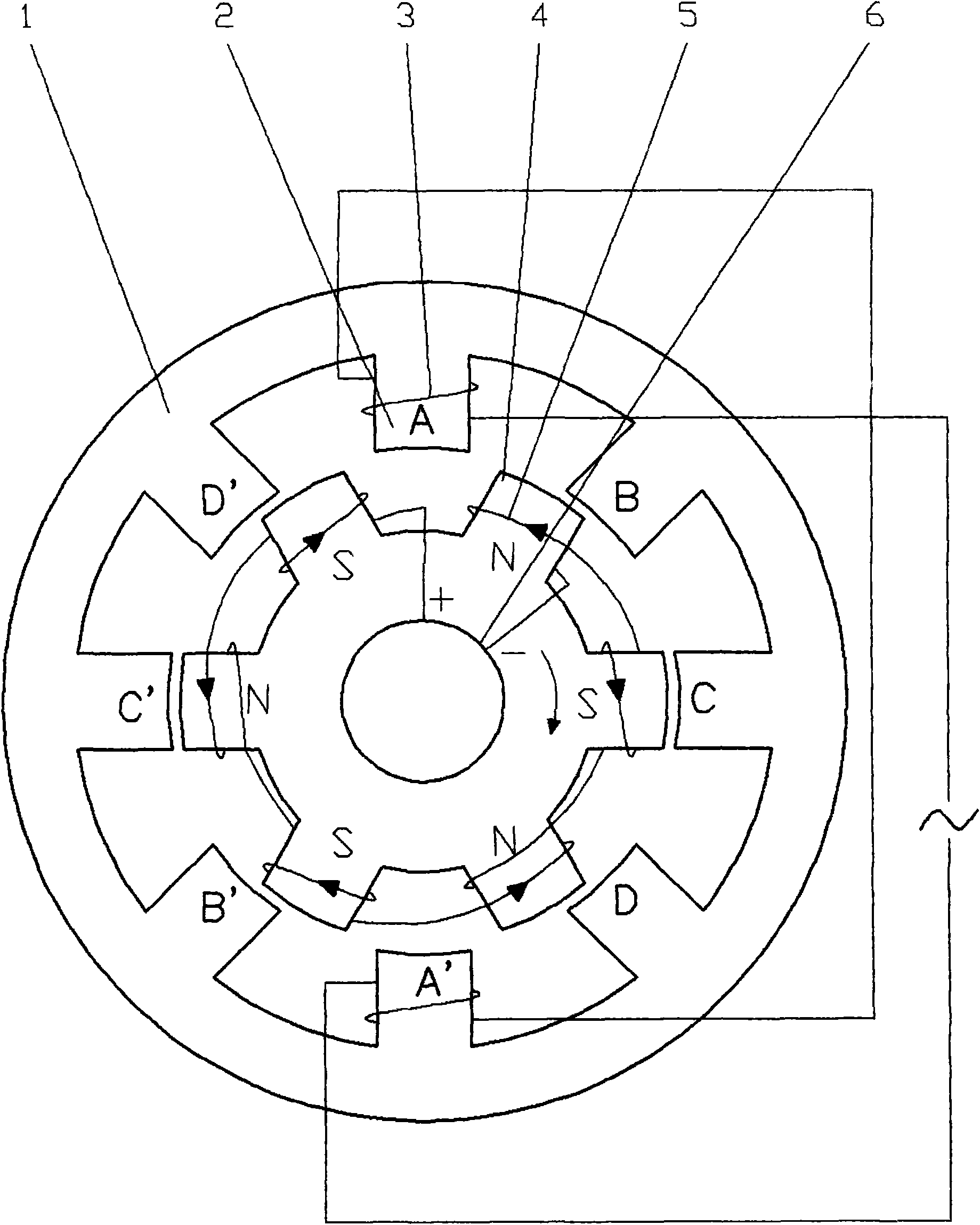
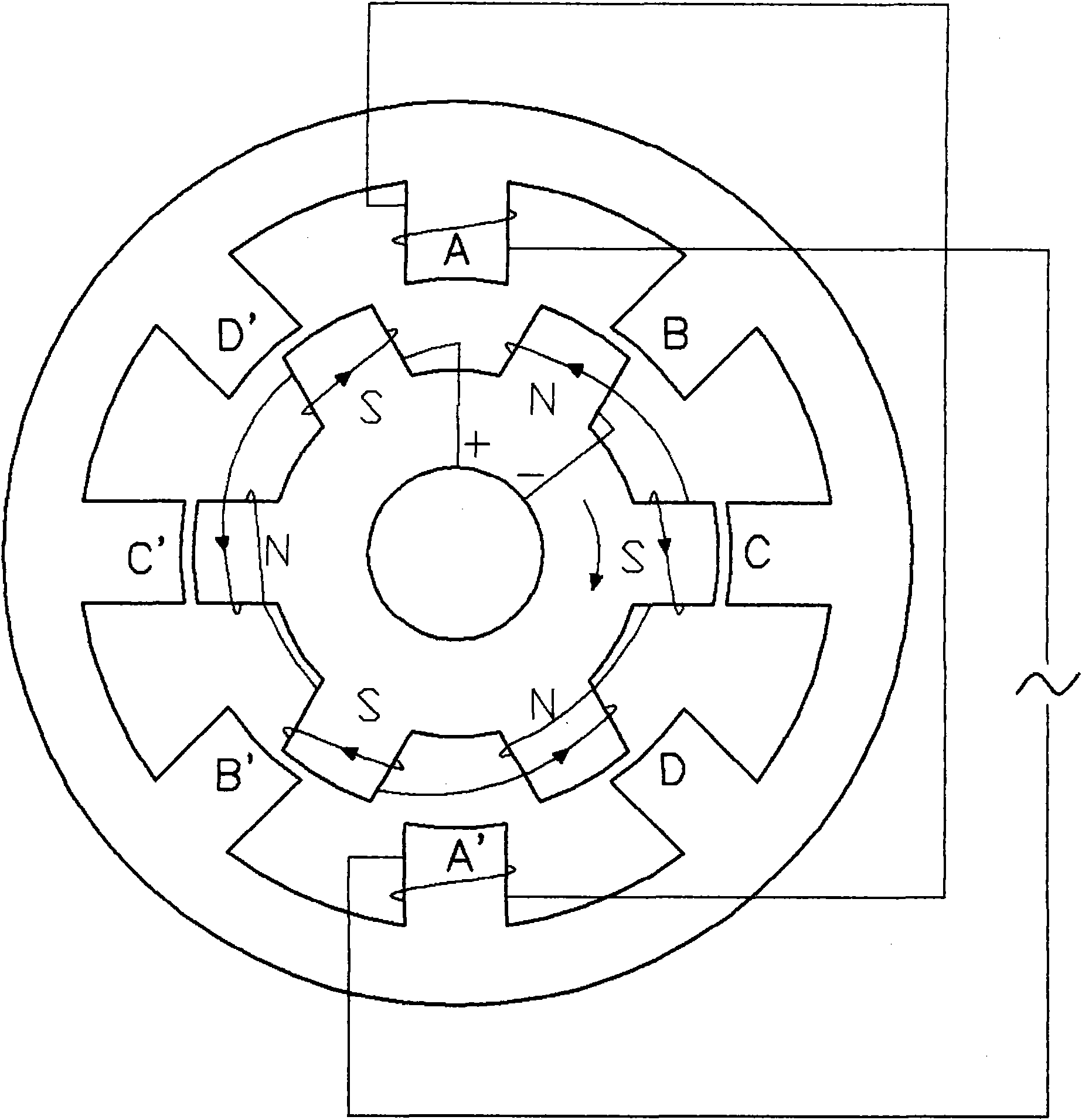
[0017] Please see attached figure 2 , On the basis of not changing the working principle of the switched reluctance motor, an independent excitation winding 5 and its control circuit are installed on the salient pole of the salient pole rotor 4. The excitation winding 5 passes through th...


PUM


Abstract

The invention discloses a switched reluctance motor with an electromotion and power generation conversion function used for an electric vehicle. The switched reluctance motor has a rotor-stator doubly salient structure. On the basis of not changing the working principle of the switched reluctance motor, an independent exciting winding and an external control circuit thereof are arranged on a rotor salient pole and the exciting winding draws power through a collector slip ring; and when in electromotion, a dip switch thereof is switched off so that a rotor winding is unloaded; when the motor obtains reaction force by the brake, the downgrade and the like of a vehicle, a master control system is fed back by a brake signal, switches off a drive circuit by a control circuit, simultaneously switches to close a charger and a circuit between the charger and a storage battery, and simultaneously switches to close the circuit between the collector slip ring and the storage battery. In such a way, the storage battery supplies the power to the exciting winding through the collector slip ring so that the rotor is converted into an excitation field of a power generator; a rotational rotor excitation field generates the power by performing alternating excitation on the armature winding of the original stator; and therefore, a real function of double purposes of electromotion and power generation on one machine is realized.

Description

technical field [0001] The invention belongs to the field of electromechanical integration, and relates to a switched reluctance motor for electric vehicles with functions of converting electric power and power generation. Background technique [0002] At present, almost all electric vehicle motors on the domestic market are permanent magnet motors, and switched reluctance motors with high performance are rarely used. Although permanent magnet motors have certain power generation functions, they can directly generate electricity under the action of reaction force. Conversely, when generating electricity, because its own structure is quite different from the structure and principle of the generator, its power generation efficiency is very low, and it has almost no use value. SUMMARY OF THE INVENTION [0003] The purpose of the present invention is to provide a switched reluctance motor for electric vehicles with the function of converting electric power and power generation...

Claims


Application Information

Patent Timeline
IPC IPC(8): H02K29/00H02P9/14
CPCY02T10/641Y02T10/64
Inventor 谢庆生
Owner 谢庆生
Why Eureka
Eureka Blog
Learn More