Method, system and device for realizing bidirectional communication by combining passive optical network with power-line carrier

A passive optical network, power line carrier technology, applied in the field of two-way communication, to achieve the effect of reducing comprehensive cost, reducing power consumption and reducing cost

Inactive Publication Date: 2011-01-12
李淑英
View PDF3 Cites 19 Cited by
  • Summary
  • Abstract
  • Description
  • Claims
  • Application Information

AI Technical Summary

Problems solved by technology

The gateway performs analog front-end processing, digital-to-analog an

Method used


Image

  • Method, system and device for realizing bidirectional communication by combining passive optical network with power-line carrier
  • Method, system and device for realizing bidirectional communication by combining passive optical network with power-line carrier
  • Method, system and device for realizing bidirectional communication by combining passive optical network with power-line carrier

Examples


Embodiment Construction

[0021] The specific implementation mode that the present invention adopts is described in detail below in conjunction with accompanying drawing:

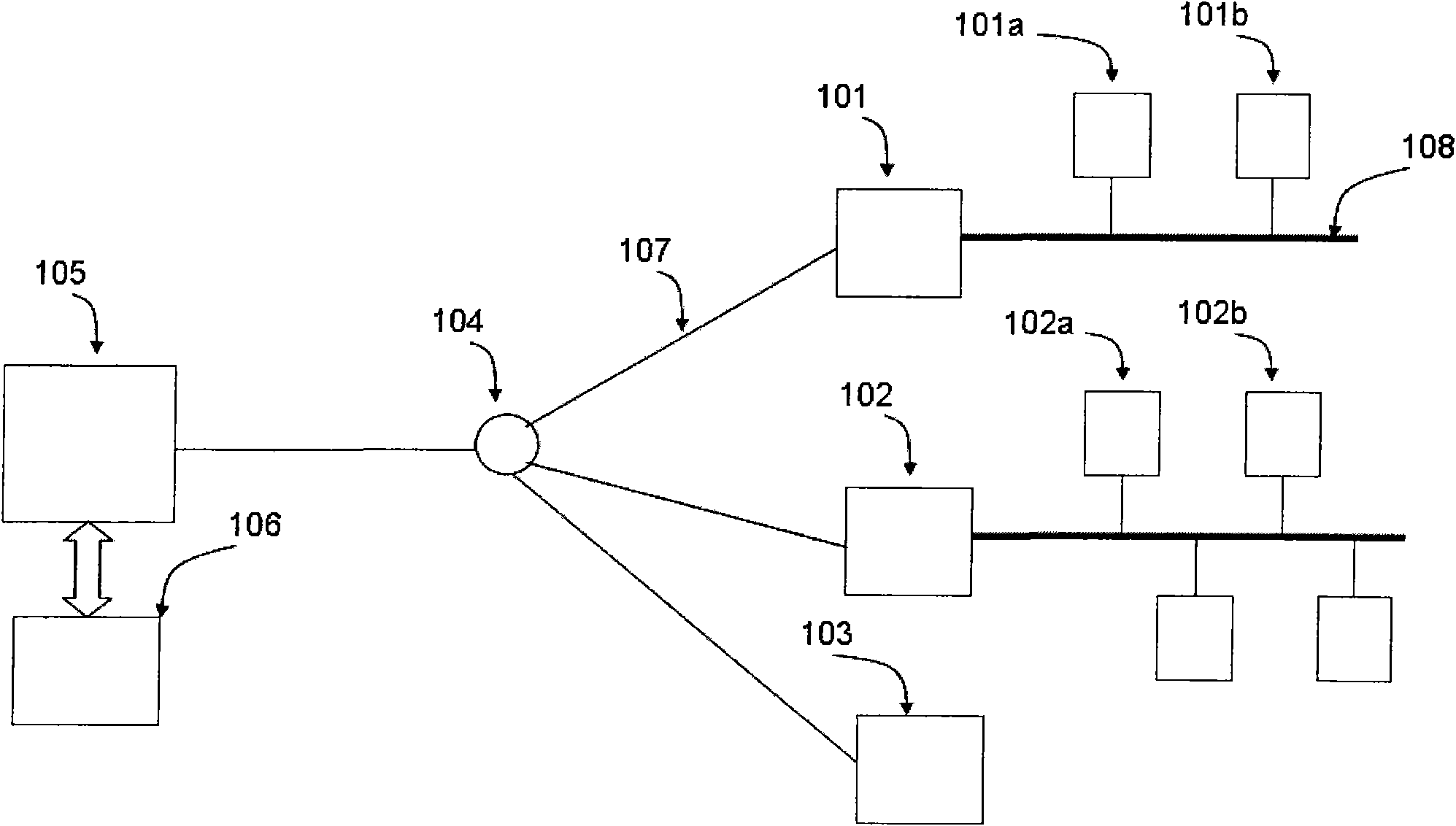
[0022] The present invention adopts a new network system in order to overcome the defects of the prior art and simplify the design of gateway nodes. Such as image 3 As shown: 101a, 101b, 102a, and 102b are terminal nodes respectively; 101, 102 are gateways, 103 is an optical network unit (ONU, Optical network unit), 104 is an optical splitter, and 105 is an optical line terminal (OLT, Optical line terminal) , 106 is the central control node, 107 is connected to the optical fiber, and 108 is the power line

[0023] End nodes 101a, 101b are connected to gateway 101 through power lines, while 102a, 102b are connected to gateway 102 through power lines. One end of the gateways 101 and 102 is connected to the terminal nodes, and the other end is connected to the OLT 105 in the form of a passive optical network through an optical fiber...


PUM


Abstract

The invention relates to a method, a system and a device for realizing communication between a terminal node and a central control node by combining a passive optical network with power-line carrier. The invention simplifies gateway protocol processing levels, thereby lowering the gateway cost and power consumption and enhancing the gateway reliability and safety. The invention can enable the system to have wide compatibility with different power-line carrier standard systems.

Description

technical field [0001] The present invention relates to the field of passive optical network (PON, Passive Optical Network) access and the field of power line carrier communication (PLC, Power Line Communication). Two-way communication between terminal nodes and central control nodes. Background technique [0002] In recent years, energy conservation and emission reduction and the utilization of new energy sources have increasingly been placed in a strategic position. People are increasingly using renewable energy such as wind energy, solar energy, and water conservancy. People also hope to avoid unnecessary waste through rational use of energy. These requirements promote the "smart" transformation of the existing grid to evolve into a smart grid. The key to this evolution is to realize information communication and timely monitoring of power generation, power transmission, power distribution, and power consumption. This requires two-way communication of information in t...

Claims


Application Information

Patent Timeline
IPC IPC(8): H04Q11/00H04B3/54H04L12/66
Inventor 董子源
Owner 李淑英
Why Eureka
Try Eureka