Method for online cleaning of air preheaters

A technology of air preheater and soot blower, which is applied in the field of rotary regenerative air heater, and can solve the problem that the soot blower has little effect on removing ammonium bisulfate deposits

Inactive Publication Date: 2011-01-19
BREEN ENERGY SOLUTIONS
View PDF13 Cites 12 Cited by
  • Summary
  • Abstract
  • Description
  • Claims
  • Application Information

AI Technical Summary

Problems solved by technology

[0015] Sootblowers as described above are rarely effective in removing ammonium bisulfate deposits

Method used


Image

  • Method for online cleaning of air preheaters
  • Method for online cleaning of air preheaters
  • Method for online cleaning of air preheaters

Examples


Embodiment Construction

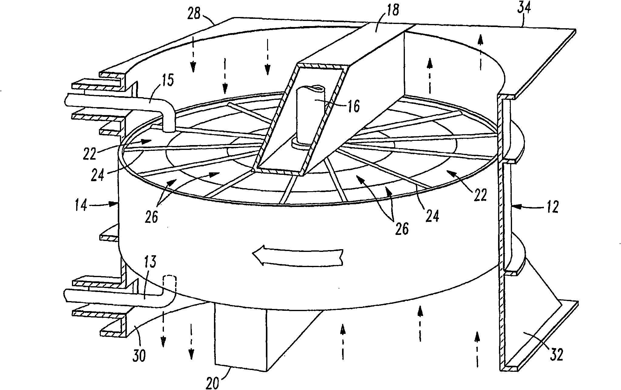
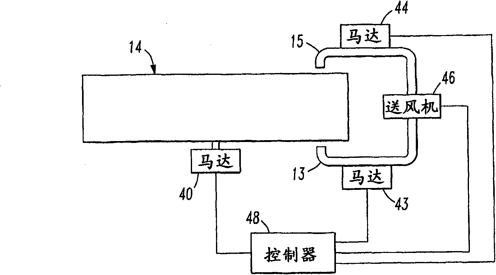
[0022] figure 1 is a perspective view of a typical air preheater with flue gas flowing in a vertical, upward or downward direction, and is used to illustrate one type of air preheater to which the present invention is applied. The present invention can be applied to horizontal, vertical (cold end at the top) and vertical inverted (cold end at the bottom) air preheaters. figure 1 A vertical air preheater is shown with the cold end at the bottom. The air preheater includes a rotor housing 12 in which a heat exchange rotor 14 is mounted. The rotor is mounted for rotation about an axis 16 extending between an upper central portion 18 and a lower central portion 20 . The rotor is divided by diaphragm plates 24 into sectors or channels 22 in which heat exchange baskets 26 are stacked. Transition duct assemblies indicated at 28 , 30 , 32 and 34 are located at the top and bottom of the air preheater, attached to the rotor housing 12 and the upper and lower center sections 18 , 20 ....


PUM


Abstract

A method of cleaning air preheaters of the type having a rotor which passes through a stream of flue gas and a stream of intake combustion air is disclosed. A soot blower is operated in step-wise fashion to blow a soot blowing medium through passageways in the rotor. The passageways are arranged in concentric rings and move at a tangential velocity which depends on the speed of the rotor and the location of the passageway relative to the center of the rotor. In the present method the speed of the rotor is adjusted in accordance with the position of the soot blower so that every passageway moves over the soot blower at the same or substantially the same tangential velocity.

Description

technical field [0001] The present invention relates to a method for cleaning rotary regenerative air heaters used in coal fired power stations. Background technique [0002] The technique of preheating air has been known and used for many years in connection with boilers to improve combustion and boiler efficiency. One such preheating technique uses a Ljungstrom air preheater. This air preheater has two ducts arranged side by side, the flue gas flows through one duct, the incoming combustion air flows through the other duct, and the two gases flow in opposite directions. The rotor is positioned to rotate about an axis between the two ducts passing through the two ducts, transferring heat from the flue gases to the combustion air. Air preheaters typically operate at a temperature high enough to prevent condensation of contaminants present in the flue gas (eg, sulfuric acid vapor) within the heat exchanger. For example, in a typical published temperature guideline for a Ju...

Claims


Application Information

Patent Timeline
Patent Type & Authority Applications(China)
IPC IPC(8): B08B5/02F23L15/00
CPCF28D19/044F28G9/005F28G15/00F28G1/16
Inventor S·托马斯C·A·洛克特
Owner BREEN ENERGY SOLUTIONS
Why Eureka
Try Eureka