Method for detecting nonzero digit compensation light-degree optical aspheric surface profile

A surface shape detection and aspheric technology, which is applied in the direction of using optical devices, measuring devices, instruments, etc., can solve the problems of manufacturing error adjustment, prolonging the construction period, increasing the cost, etc., achieving simple data processing and mathematical operations, and low detection costs. , the effect of shortening the test time

Inactive Publication Date: 2011-01-19
CHANGCHUN INST OF OPTICS FINE MECHANICS & PHYSICS CHINESE ACAD OF SCI
View PDF2 Cites 34 Cited by
  • Summary
  • Abstract
  • Description
  • Claims
  • Application Information

AI Technical Summary

Problems solved by technology

However, for aspheric components, it is generally necessary to specially design and customize compensators or use auxiliary components such as computational holograms (CGH) to perform interferometric measurements through zero compensation, which not only increases the cost and prolongs the construction period, but also assists Components will introduce certain manufacturing errors and assembly errors

Method used


Image

  • Method for detecting nonzero digit compensation light-degree optical aspheric surface profile
  • Method for detecting nonzero digit compensation light-degree optical aspheric surface profile
  • Method for detecting nonzero digit compensation light-degree optical aspheric surface profile

Examples


Embodiment Construction

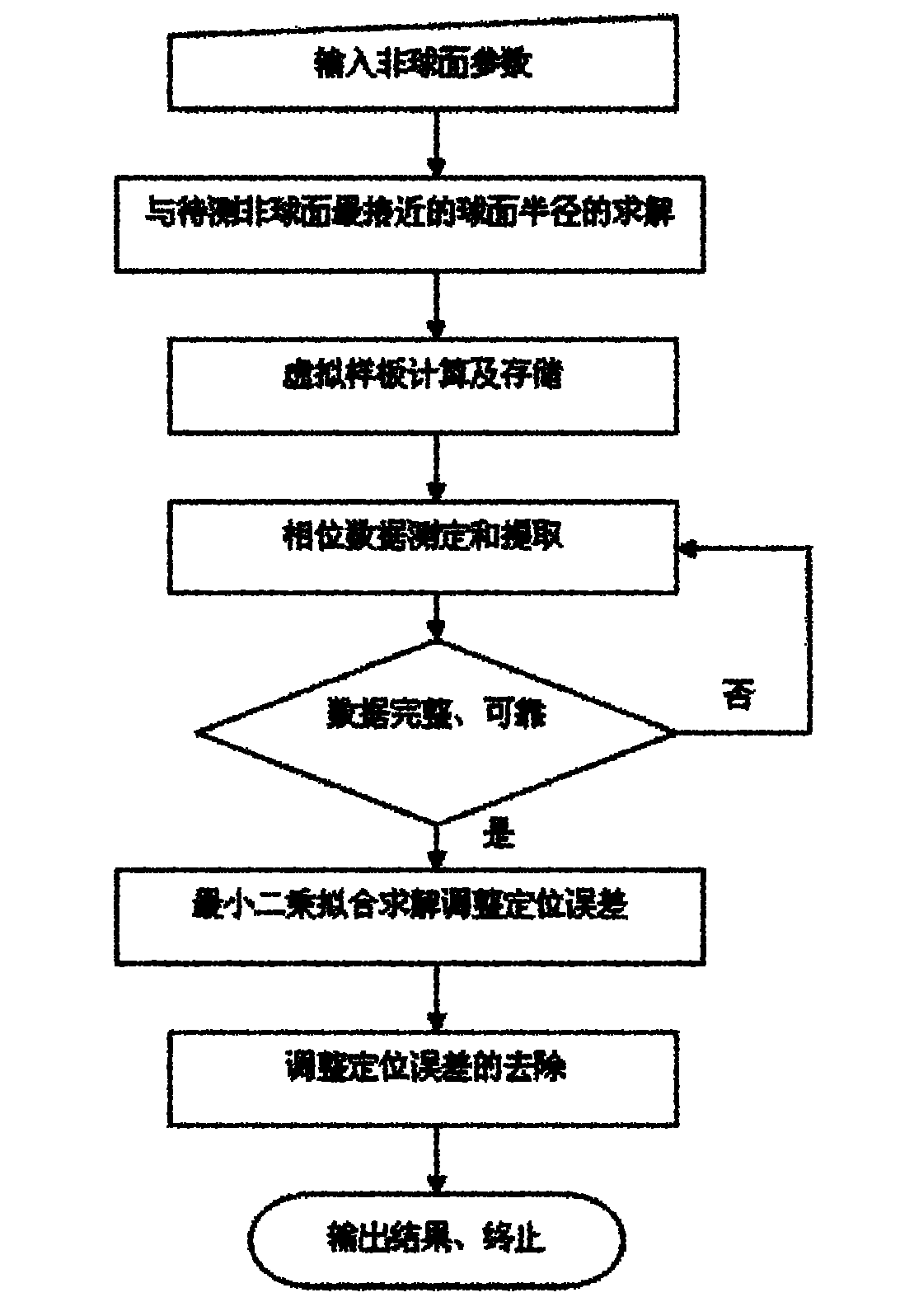
[0021] Such as figure 1 As shown, the device for realizing the non-zero compensation shallow optical aspheric surface shape detection method of the present invention includes an interferometer 1, a transmission ball 2 and a computer 7. The transmission sphere 2 is fixed at the light hole of the interferometer 1. The parallel light emitted by the interferometer 1 is transformed into a standard spherical wave by the transmission sphere 2. The standard spherical wave is incident on the aspheric surface 3 to be measured as a reference spherical wave. Measure the reflection of the aspheric surface 3 and return to the interferometer 1. The optical aspheric surface 3 to be measured is fixed on the first adjustment mechanism 4, and the interferometer 1 is fixed on the second adjustment mechanism 5. The computer 7 controls the action of the first adjustment mechanism 4 through the first numerical control device 8 to adjust the translation and rotation of the optical aspheric surface 3 t...


PUM


Abstract

The invention relates to a method for detecting a nonzero digit compensation light-degree optical non-spherical profile. The method comprises the following steps of: calculating the value of z(x, y)-s(x, y, r), wherein z(x, y) is the rise distribution of an aspheric surface along the direction of an optical axis, and s(x, y, r) is the rise distribution of a spherical surface closest to the aspheric surface to be detected along the direction of the optical axis; converting emergent parallel light of an interferometer into standard spherical waves by utilizing a transmission ball and using the standard spherical waves as reference spherical waves; adjusting the position of the aspheric surface to be detected to ensure that the circle center of the spherical surface closest to the aspheric surface to be detected coincides with a focus point of converging the reference spherical waves; detecting phase distribution data of interference fringes formed by the optical waves reflected by the aspheric surface to be detected and the reference spherical waves by utilizing the interferometer; and rejecting the value of the z(x, y)-s(x, y, r) and an adjusting and positioning error epsilon (x, y) from the phase distribution data of the interference fringes to obtain the profile error distribution e(x, y) of the aspheric surface. The invention can realize the detection of large-caliber concave and convex light-degree aspheric surface profiles with high resolution and high precision and has the advantages of low detection cost and short detection cost.

Description

Technical field [0001] The invention relates to a method for detecting the shape of an optical aspheric surface, in particular to a method for detecting the shape of a non-zero compensation shallow optical aspheric surface. Background technique [0002] At present, there are many methods for detecting aspherical elements, which are mainly divided into contact measurement, shadow method, laser scanning method, and interferometric method. Contact measurement mainly uses a profiler or a three-coordinate measuring instrument to measure multiple discrete points on the optical element, and then process the data to obtain the surface error by fitting. This method is mainly used for the detection of optical element grinding and rough polishing stages, and the contact between the probe and the element may bring certain scratches to the surface. The shading method is mainly divided into the knife-edge method and the Hartman method (diaphragm method). This method mainly observes the shadow...

Claims


Application Information

Patent Timeline
Patent Type & Authority Applications(China)
IPC IPC(8): G01B11/24
Inventor 王孝坤郑立功张学军
Owner CHANGCHUN INST OF OPTICS FINE MECHANICS & PHYSICS CHINESE ACAD OF SCI
Why Eureka
Try Eureka