
Gas engine using low calorie gas fuel

A low calorific value gas and gas engine technology, which is applied to combustion engines, internal combustion piston engines, gaseous engine fuels, etc., and can solve problems that cannot be directly applied to engines

Active Publication Date: 2011-01-19
MITSUBISHI HEAVY IND ENGINE & TURBOCHARGER LTD
View PDF1 Cites 13 Cited by
  • Summary
  • Abstract
  • Description
  • Claims
  • Application Information

AI Technical Summary

Problems solved by technology

[0025] Therefore, as described in Patent Document 2, a mechanism is used in which a lean fuel mixture is filled with a first fuel that forms a lean mixture and a second fuel that burns faster than the first fuel and has a stronger ignition performance. The main combustion chamber, filling the secondary combustion chamber with the second fuel, using the first fuel that forms a lean mixture and the second fuel that burns faster than the first fuel and has a stronger ignition performance, and fills the main combustion chamber with a lean mixture 1. Fill the secondary combustion chamber with the second fuel, but this mechanism cannot be directly applied to engines fueled by low calorific value gas with methane concentration as low as 50%

Method used


Image

  • Gas engine using low calorie gas fuel
  • Gas engine using low calorie gas fuel
  • Gas engine using low calorie gas fuel

Examples


no. 1 approach

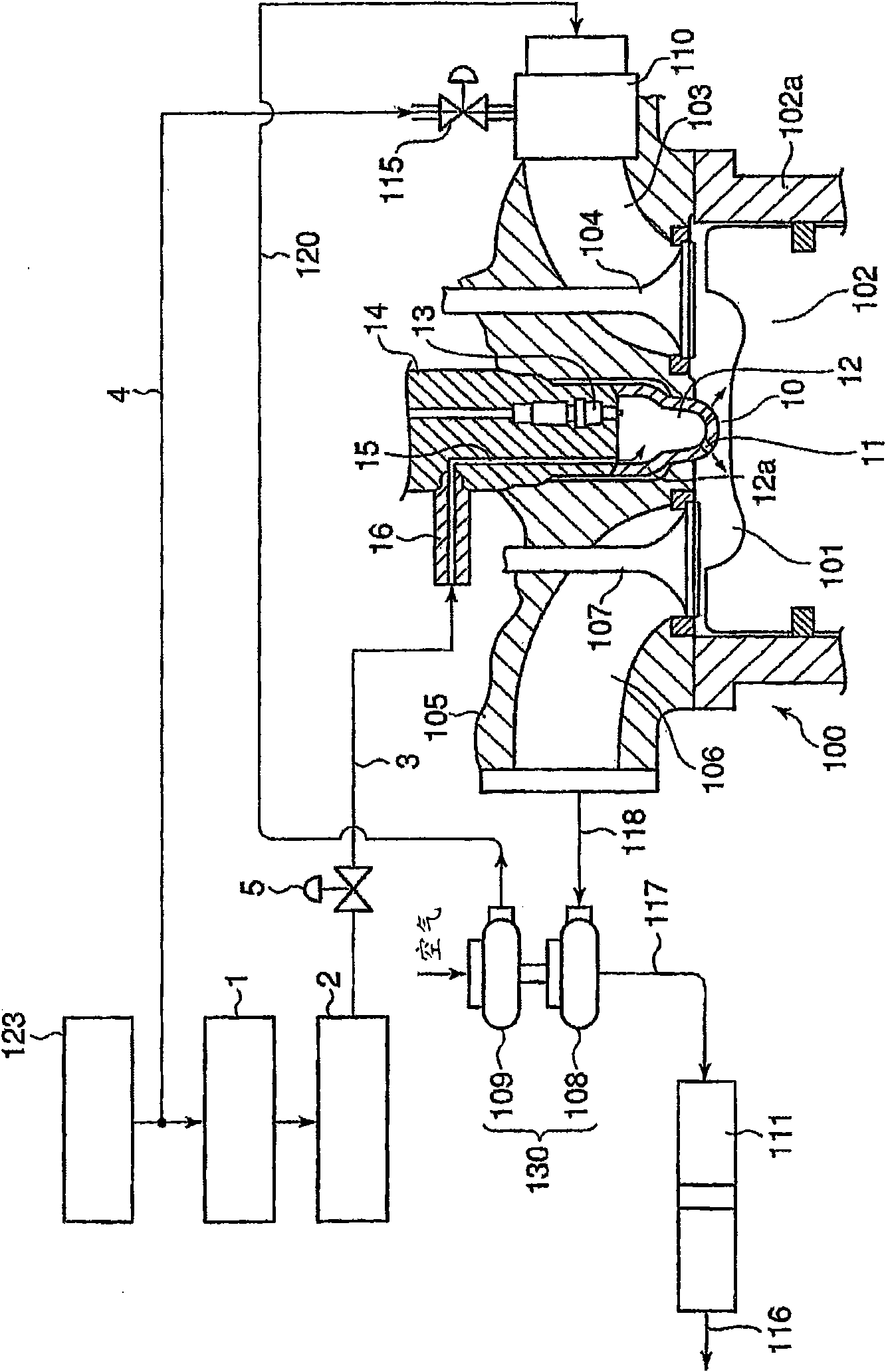
[0052] figure 1 It is a block diagram showing a structure around a combustion chamber of a gas engine using low calorific value gas as fuel according to the first embodiment of the present invention.

[0053] The fuel gas uses coal mine methane and other methane concentrations as low as 50% or less, and the calorific value is only about 30% of the low calorific value gas (refer to Figure 4 ), the low calorific value gas is stored in the low calorific value gas supply source 123.

[0054] The outlet of the low calorific value gas supply source 123 is connected to the PSA processing device 1 .

[0055] In this PSA treatment device 1, implement pressure swing adsorption type treatment (PSA treatment), that is, the low calorific value gas of only about 30% of the gas engine with conventional calorific value (refer to Figure 4 ) is pressurized and made to flow through an adsorbent such as zeolite, and impurities are separated by adsorption to obtain methane gas with a concentr...

no. 2 approach

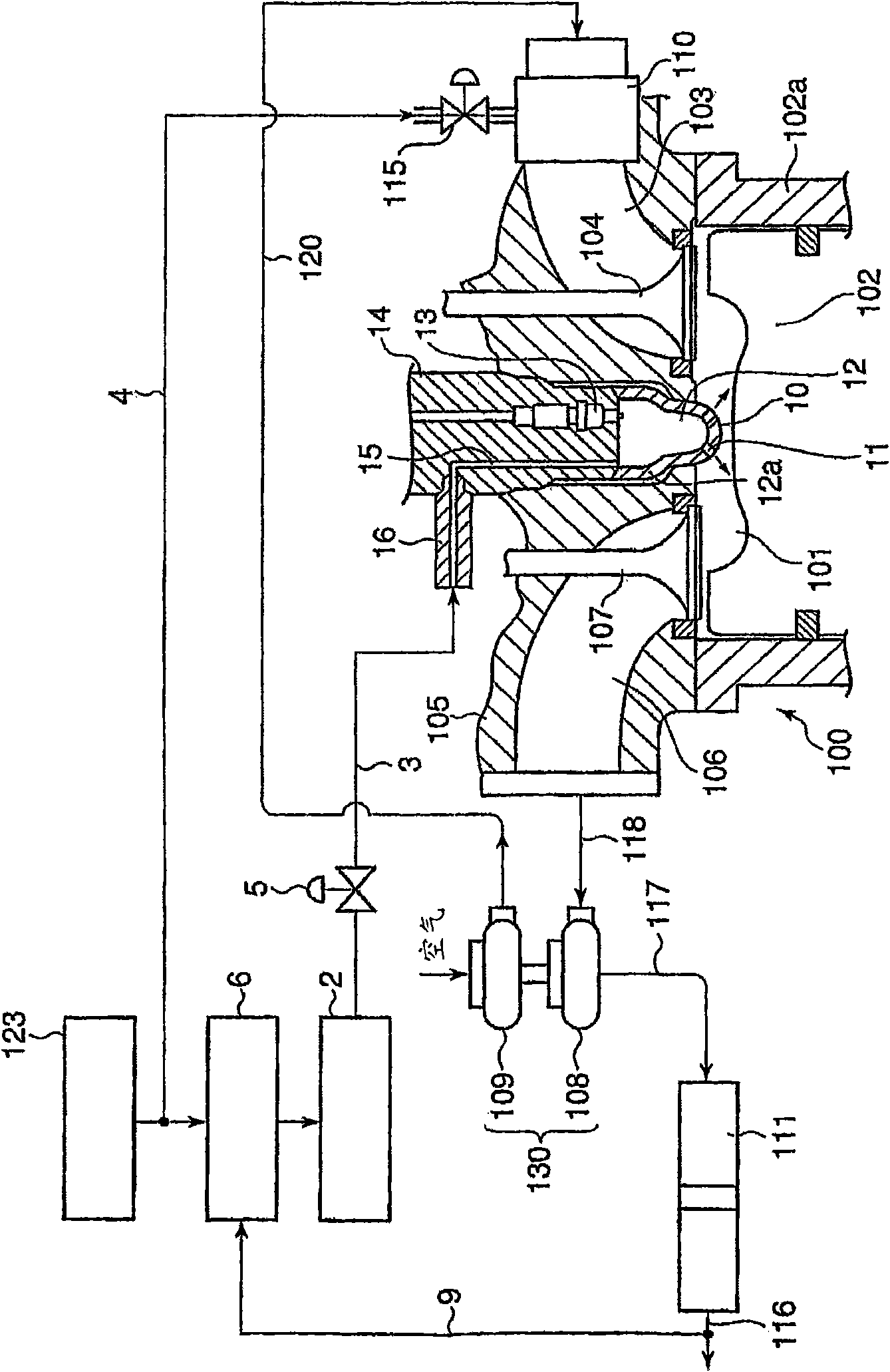
[0078] figure 2 It is a block diagram showing a structure around a combustion chamber of a gas engine using a low calorific value gas as fuel according to a second embodiment of the present invention.

[0079] In this second embodiment, the PSA treatment device 1 in the first embodiment is replaced with a temperature swing adsorption treatment device (TSA treatment device) 6 .

[0080] That is, in the second embodiment, the low calorific value gas from the low calorific value gas supply source 123 is sent to the TSA processing apparatus 6 .

[0081] That is, in this TSA treatment device 6, as mentioned above, implement the temperature swing adsorption type treatment (TSA treatment), that is, the low calorific value gas with a calorific value of only about 30% of that of a gas engine with a conventional calorific value (refer to Figure 4 ), through adsorption and separation of impurities at a temperature increase of about 200°C to obtain methane gas with a concentration of 1...


PUM


Abstract

Provided with a gas engine using low calorie gas, e.g. coal mine methane, having the concentration of methane of 50% or less as fuel in which the concentration of methane is increased so that low calorie gas injected into a subchamber can be ignited by an ignition plug and combusted. The gas engine using low calorie gas having the concentration of methane of 50% or less as fuel performs pressure swing adsorption treatment (PSA treatment) for obtaining methane gas having high concentration of methane by carrying low calorie gas into a PSA treatment unit and separating impurities from the low calorie gas by adsorption, and the gas subjected to such a PSA treatment is introduced into the prechamber where the gas is ignited by an ignition plug and combusted.

Description

technical field [0001] The invention relates to a gas engine using low calorific value gas fuel, which uses coal mine methane and other low calorific value gas whose methane concentration is as low as 50% or less as fuel, arranges spark plugs in the auxiliary combustion chamber, and injects the low calorific value gas into the auxiliary combustion chamber And through the ignition of the spark plug, the ignition flame produced by ignition and combustion in the auxiliary combustion chamber is sprayed to the main combustion chamber through the communication hole connecting the auxiliary combustion chamber and the main combustion chamber, and the flame is connected to the main combustion chamber through the ejected flame. The secondary combustion chamber side is separated and combusted by the mixed gas in the main combustion chamber formed by the low calorific value gas sucked in through the air inlet. Background technique [0002] A gas engine that uses coal mine methane and ot...

Claims


Application Information

Patent Timeline
Patent Type & Authority Applications(China)
IPC IPC(8): F02M21/02F02B19/10F02B19/12F02B19/16F02B43/00F02B43/04F02D19/02F02D19/08F02M27/02
CPCF02M21/0215F02B43/10Y02T10/125F02D19/02F02M25/0709F02B19/108F02B43/04Y02T10/16F02M21/0227Y02T10/126Y02T10/32F02B51/06F02B19/12F02B19/18F02M21/0284B01D53/0462B01D53/053B01D2253/108B01D2256/245F02D19/023F02M26/06Y02T10/12Y02T10/30
Inventor 柚木晃广
Owner MITSUBISHI HEAVY IND ENGINE & TURBOCHARGER LTD
Learn More