
Method for transforming crude argon column condenser with non-condensable gas discharging pipe, and crude argon column condenser

A crude argon tower and discharge pipe technology, which is applied in chemical instruments and methods, inert gas compounds, inorganic chemistry, etc., can solve the problems of increasing equipment materials and processing and manufacturing costs, increasing the processing difficulty of the crude argon tower condenser, and non-condensable gas discharge Tubes are prone to leaks and other problems, achieving the effect of reducing material costs, reducing man-hour costs, and improving safety factors

Inactive Publication Date: 2012-01-11
HENAN KAIYUAN AIR SEPARATION GRP CO LTD
View PDF0 Cites 0 Cited by
  • Summary
  • Abstract
  • Description
  • Claims
  • Application Information

AI Technical Summary

Problems solved by technology

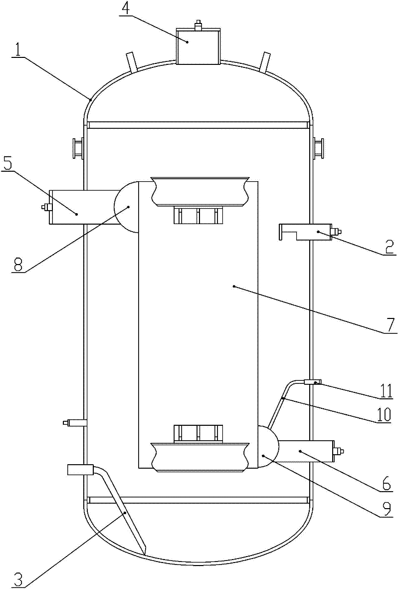
[0004]The existing crude argon tower condenser with non-condensable gas discharge pipe has two disadvantages: one is that the crude argon tower The processing difficulty of the condenser is increased, which increases the material and processing and manufacturing costs of the equipment
The second is that the non-condensable gas discharge pipe is very prone to leakage due to structural reasons, and once a leak occurs, even an extremely small leak will cause the failure of the entire air separation unit
[0006]Because of the shortcomings of the original crude argon tower condenser with non-condensable gas discharge pipe, such as difficult processing, high production cost and easy leakage, we have been Efforts are being made to design a new type of crude argon column condenser, hoping that the new condenser can avoid a series of shortcomings of the original condenser

Method used


Image

  • Method for transforming crude argon column condenser with non-condensable gas discharging pipe, and crude argon column condenser
  • Method for transforming crude argon column condenser with non-condensable gas discharging pipe, and crude argon column condenser
  • Method for transforming crude argon column condenser with non-condensable gas discharging pipe, and crude argon column condenser

Examples


Embodiment 1

[0031] Embodiment 1: A modification method for a crude argon tower condenser with a non-condensable gas discharge pipe. The existing crude argon tower condenser with a non-condensable gas discharge pipe includes a closed tank and a plate installed in the tank Finned heat exchanger, the tank body is provided with liquid air inlet pipe, liquid air outlet pipe, liquid air steam outlet pipe, the plate bundle body, upper head, and lower head contained in the plate-fin heat exchanger , argon inlet pipe, and liquid argon outlet pipe; the upper head of the plate-fin heat exchanger is connected with the argon inlet pipe to pass through the tank, and the lower head of the lower part of the plate-fin heat exchanger is Connect the liquid argon outlet pipe through the tank body, the centerline of the liquid argon outlet pipe is lower than the centerline of the lower head, the upper part of the lower head is connected to the non-condensable gas discharge pipe, and passes through the tank bod...

Embodiment 2

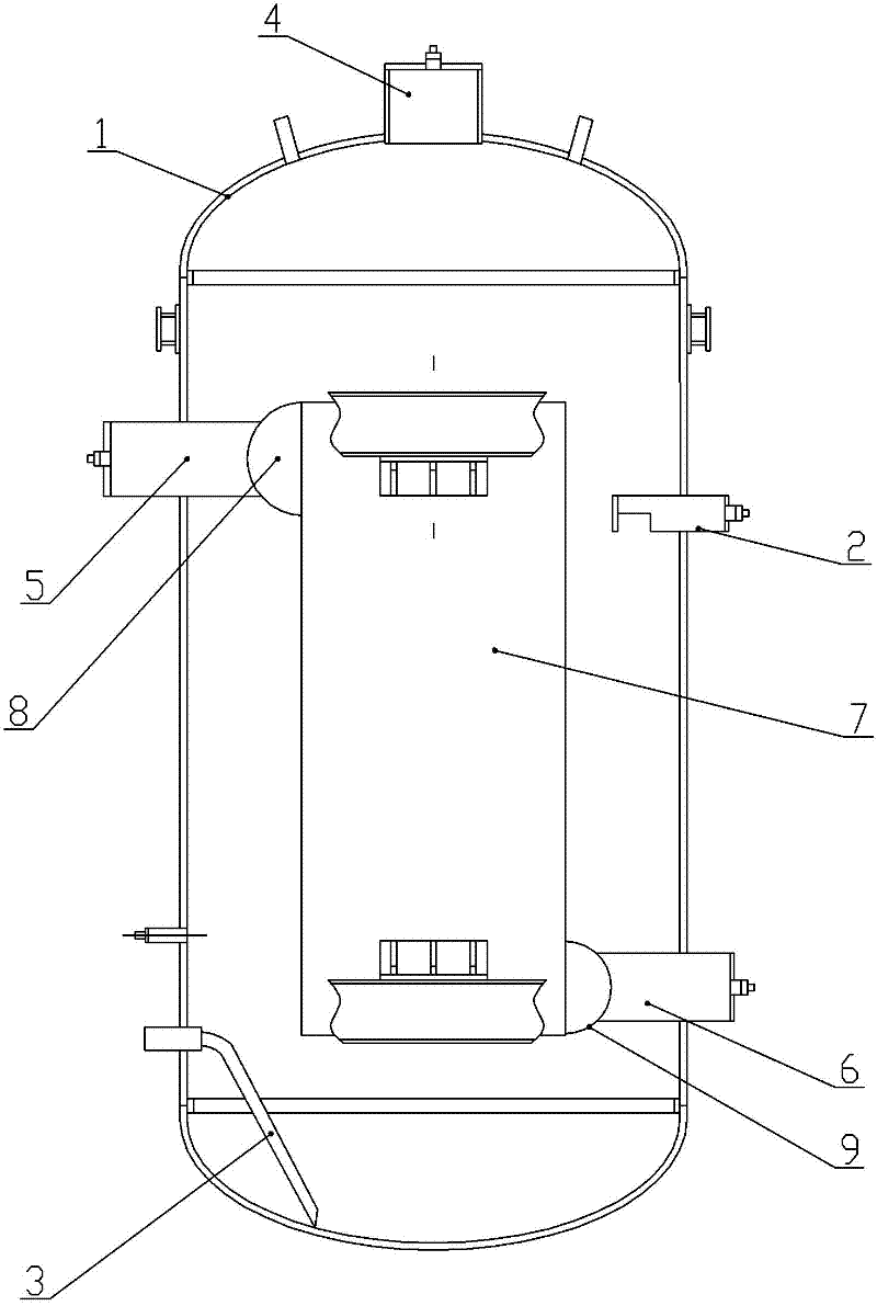
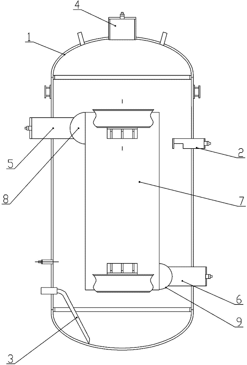
[0039] Embodiment two: see figure 2 , a crude argon tower condenser in the figure, including a closed tank body and a plate-fin heat exchanger installed in the tank body, the tank body is provided with a liquid air inlet pipe, a liquid air outlet pipe, and a liquid air outlet pipe. Steam outlet pipe, the plate bundle body, upper head, lower head, argon gas inlet pipe, and liquid argon outlet pipe contained in the plate-fin heat exchanger; the upper head of the plate-fin heat exchanger Connect the argon inlet pipe to pass through the tank body, connect the liquid argon outlet pipe to the lower head of the plate-fin heat exchanger and pass through the tank body, the center line of the liquid argon outlet pipe and the center of the lower head Line coincidence, the diameter of the liquid argon outlet pipe is 1.3-2.0 times the standard size designed according to national or industry standards and combined with production capacity requirements, and the value is preferably 1.5 times...


PUM


Abstract

The invention relates to a method for transforming a crude argon column condenser with a non-condensable gas discharging pipe, and the crude argon column condenser. The method comprises the steps of: removing the non-condensable gas discharging pipe, and enclosing through holes at connecting parts of the gas discharging pipe, a lower end socket and a tank body; changing a liquid argon outlet pipeinto a liquid argon outlet pipe with a caliber 1.3-2.0 times more than that of the former; and moving up the center line of the liquid argon outlet pipe to ensure that the center line is superposed with the center line of the lower end socket. The transformed crude argon column condenser has the advantages of easy processing, low cost and non-leakage.

Description

[0001] technical field [0002] The invention relates to the technical field of air separation argon condensation and purification, in particular to a method for reforming a crude argon tower condenser with a non-condensable gas discharge pipe and the crude argon tower condenser. Background technique [0003] At present, the condensers of the crude argon towers used in the air separation industry are all equipped with non-condensable gas discharge nozzles. figure 1 Shown is a schematic diagram of the condenser structure of the crude argon column with a non-condensable gas discharge nozzle originally used: [0004] The existing crude argon tower condenser with a non-condensable gas discharge pipe comprises a closed tank body and a plate-fin heat exchanger installed in the tank body, and the tank body is provided with a liquid air inlet pipe, an outlet pipe, Liquid-air steam outlet pipe, the plate bundle body, upper head, lower head, argon gas inlet pipe, and liquid argon out...

Claims


Application Information

Patent Timeline
Patent Type & Authority Patents(China)
IPC IPC(8): C01B23/00
Inventor 张冰
Owner HENAN KAIYUAN AIR SEPARATION GRP CO LTD
Learn More