Self-driven joint

A self-driving, joint technology, applied in electric components, synchronous motors with static armatures and rotating magnets, electromechanical devices, etc., can solve the problem of a large number of joints, and achieve simple joint structure, small size, and fewer components. Effect

Active Publication Date: 2011-01-26
伶机(上海)驱动技术中心(有限合伙)
View PDF6 Cites 10 Cited by
  • Summary
  • Abstract
  • Description
  • Claims
  • Application Information

AI Technical Summary

Problems solved by technology

Therefore, this type of joint is not suitable for manufacturing compact structures, a large number of joints, and applications that require active drive and sensor control

Method used


Image

  • Self-driven joint
  • Self-driven joint
  • Self-driven joint

Examples


Embodiment 1

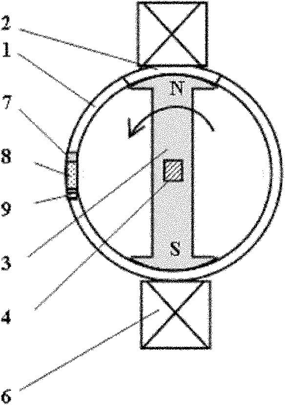
[0029] Such as figure 1 As shown, the intelligent self-driven joint of the present invention includes: a sleeve 1, a magnetic induction device composed of a structural permanent magnet 3 and a rotating output rod 4 fixedly connected thereto, and an electromagnetic coil 6, a fastener 7, a magnetostrictive material The body 8 is tightly pressed on the magnetic field generating device composed of the piezoelectric or compressive strain material connecting body 9, wherein: the magnetic induction device is installed inside the casing 1 while rotating along the axis of the casing 1, and the magnetic field generating device is fixedly arranged outside the casing 1. A pair of electromagnetic coils 6 with opposite polarities are relatively arranged on the outer wall of the sleeve 1, and the magnetostrictive piezoelectric transducer composed of a fastener 7 and a magnetostrictive material body 8 tightly pressed on a piezoelectric or compressively strained material body 9 The sensing dev...

Embodiment 2

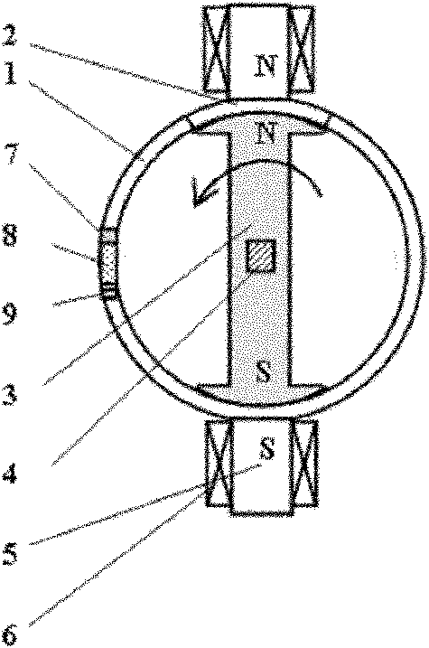
[0040] In this embodiment, on the basis of Embodiment 1, a second pair of electromagnetic coils 11 and a second yoke 10 are added, wherein: the second pair of electromagnetic coils 11 with opposite polarities and the first pair of electromagnetic coils 6 with opposite polarities are arranged alternately The outer wall of casing 1.

[0041] Embodiment 2 works by at first counteracting the permanent magnetic attraction force of the initial structure permanent magnet 3 acting on the magnetic material body 2 in the casing 1 by first energizing the electromagnetic coil on the first yoke 5, and then by applying power to the second yoke 10 The electromagnetic coil 11 is supplied with a reverse current, and under the joint action of the electromagnetic repulsion force of the magnetic first yoke iron 5 and the electromagnetic attraction force of the second yoke iron 10, the structural permanent magnet 3 deflects corresponding to the placement angle of the second yoke iron 10, And due t...

Embodiment 3

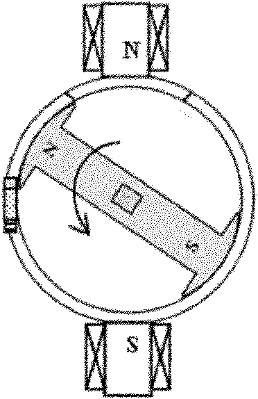
[0044] Such as Figure 6 As shown, the present embodiment adopts the first yoke 5 whose section is an L-shaped structure;

[0045] When this embodiment is working, all its constituent elements and driving action mode are the same as Embodiment 1, but for this working mode, the normal line of the two ends of the first yoke 5 is at an angle of 90 degrees; at the initial position, the first yoke 5 One end surface normal of 5 is coincident ( / perpendicular) or vertical ( / coincident) with the axis of the structural permanent magnet 3 lengthwise direction, such as Figure 6 location shown. Combined with the driving process of working mode 1, in this working mode, the structural permanent magnet 3 can realize the reciprocating rotation driving action of 90 degrees of rotation.


PUM


Abstract

The invention discloses a self-driven joint, which belongs to the technical field of driving sensing control. The self-driven joint comprises a sleeve, a structural permanent magnet and a magnetic field generating device. The structural permanent magnet is arranged in the sleeve in a way of rotating around the axis of the sleeve. The magnetic field generating device is fixedly arranged outside the sleeve and comprises a magnetostrictive piezoelectric sensor and corresponding electromagnetic coils, wherein the plurality of pairs of corresponding electromagnetic coils with opposite polarities are oppositely arranged on the outer wall of the sleeve; and the magnetostrictive piezoelectric sensor is arranged on the side wall of the sleeve. The self-driven joint has a compact structure and high structural strength and can acquire sensor electric signal conveniently without being driven by any power supply.

Description

technical field [0001] The present invention relates to a device in the technical field of drive sensing control, in particular to a self-driven joint based on the compound action of permanent magnet, magnetostrictive and piezoelectric materials or devices. Background technique [0002] Traditional joint mechanisms are all passively driven joint devices, and their functions are only for connection and transmission. The realization of the start-up process requires the action of an external motor. After searching the existing technology, it is found that Chinese Patent No. 20092025552.3 records a kind of "mechanical joint". Since this technology is only a simple mechanical mechanism, the structure is relatively complicated and there are many components. For similar joint devices, the action process needs to be used in conjunction with an external motor, and the degree or process of action can usually only be realized through an external sensing system. Therefore, this type o...

Claims


Application Information

Patent Timeline
Patent Type & Authority Applications(China)
IPC IPC(8): F16M11/00F16M11/06F16M11/18
CPCH02K21/12H02K11/0021H02K11/215
Inventor 杨斌堂孟光
Owner 伶机(上海)驱动技术中心(有限合伙)
Why Eureka
Try Eureka