
Full-automatic bearing grease feeder

A fully automatic, bearing technology, applied to engine components, engine lubrication, mechanical equipment, etc., can solve problems such as difficult processing, difficult adjustment, difficult maintenance, etc., to achieve the effect of saving complex parts, simple processing and manufacturing, and saving manpower and material resources

Inactive Publication Date: 2011-01-26
SHANDONG XUNJIE PRECISION EQUIP
View PDF4 Cites 17 Cited by
  • Summary
  • Abstract
  • Description
  • Claims
  • Application Information

AI Technical Summary

Problems solved by technology

[0002] The existing bearing greaser disc adopts a landslide structure, relying on steel plates to form a material path, the structure is complex, and processing is difficult. It is difficult to adjust when changing the model, the vibration is large, and the noise is large. Manpower; the oil injection valve part adopts the purchased cylinder, which is assembled with the purchased valve body. The whole looks patchy, with complex shape, large volume, long oil passage, low efficiency, and it is not easy to wipe when there is dust or other dirt; frame The welded steel pipe structure is used, which wastes materials. The overall structure is complex, consumes a lot of energy, and installation, commissioning, and maintenance are difficult. Due to the lack of various links, the overall volume is large, the appearance is uncoordinated, and the efficiency is low. The output is only more than 50 sets / min.
Currently, there is no good solution

Method used


Image

  • Full-automatic bearing grease feeder
  • Full-automatic bearing grease feeder
  • Full-automatic bearing grease feeder

Examples


Embodiment Construction

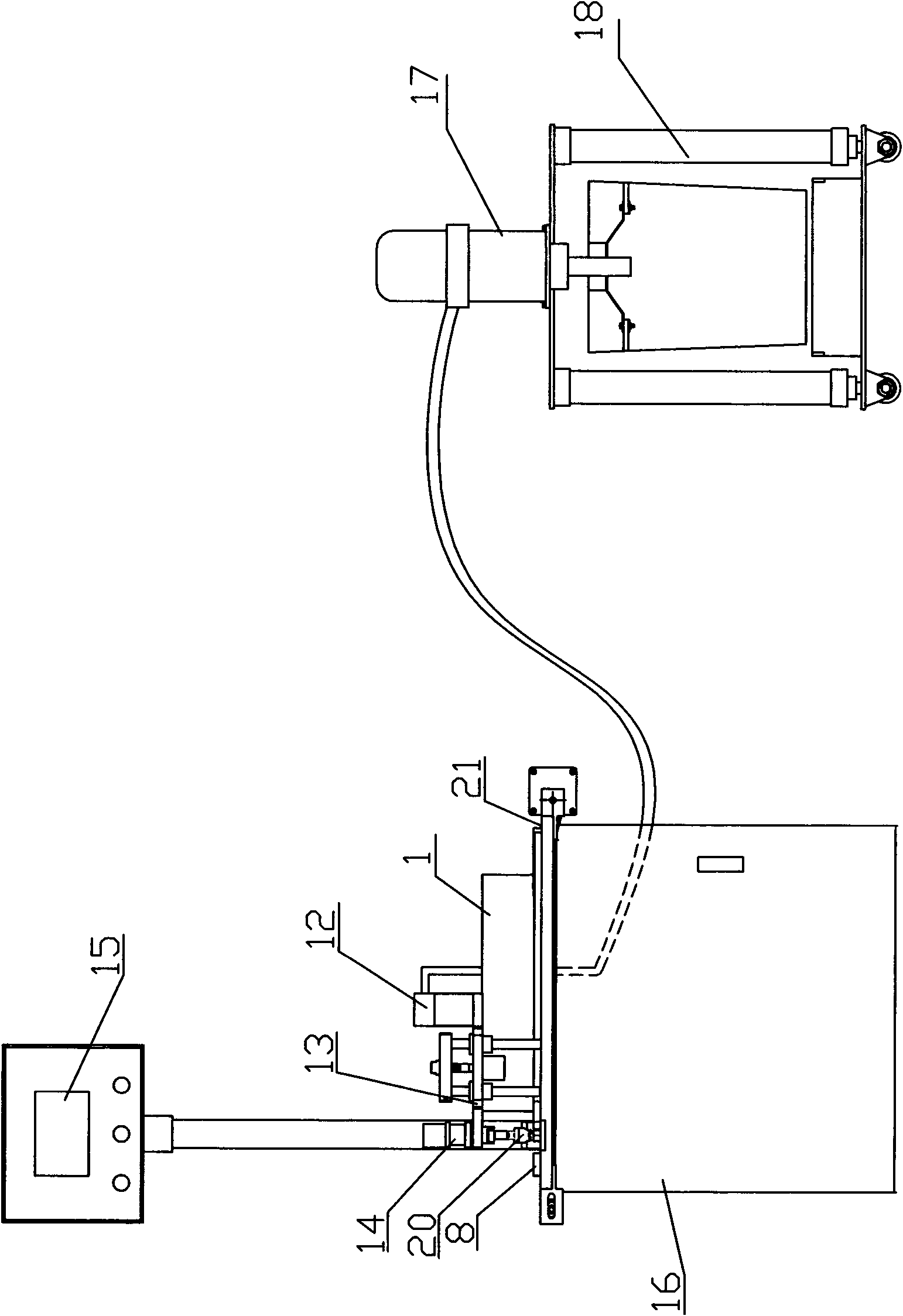
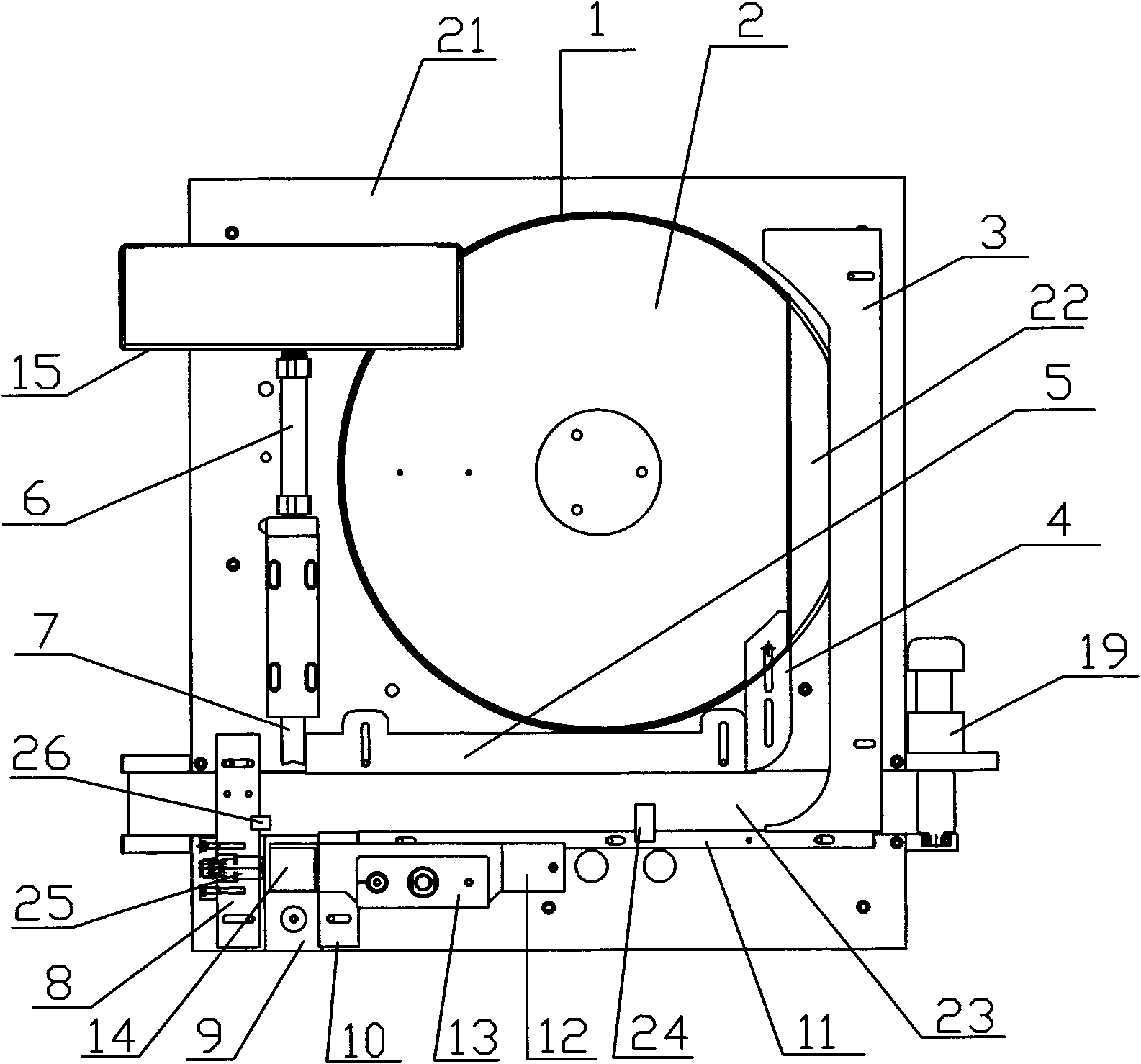
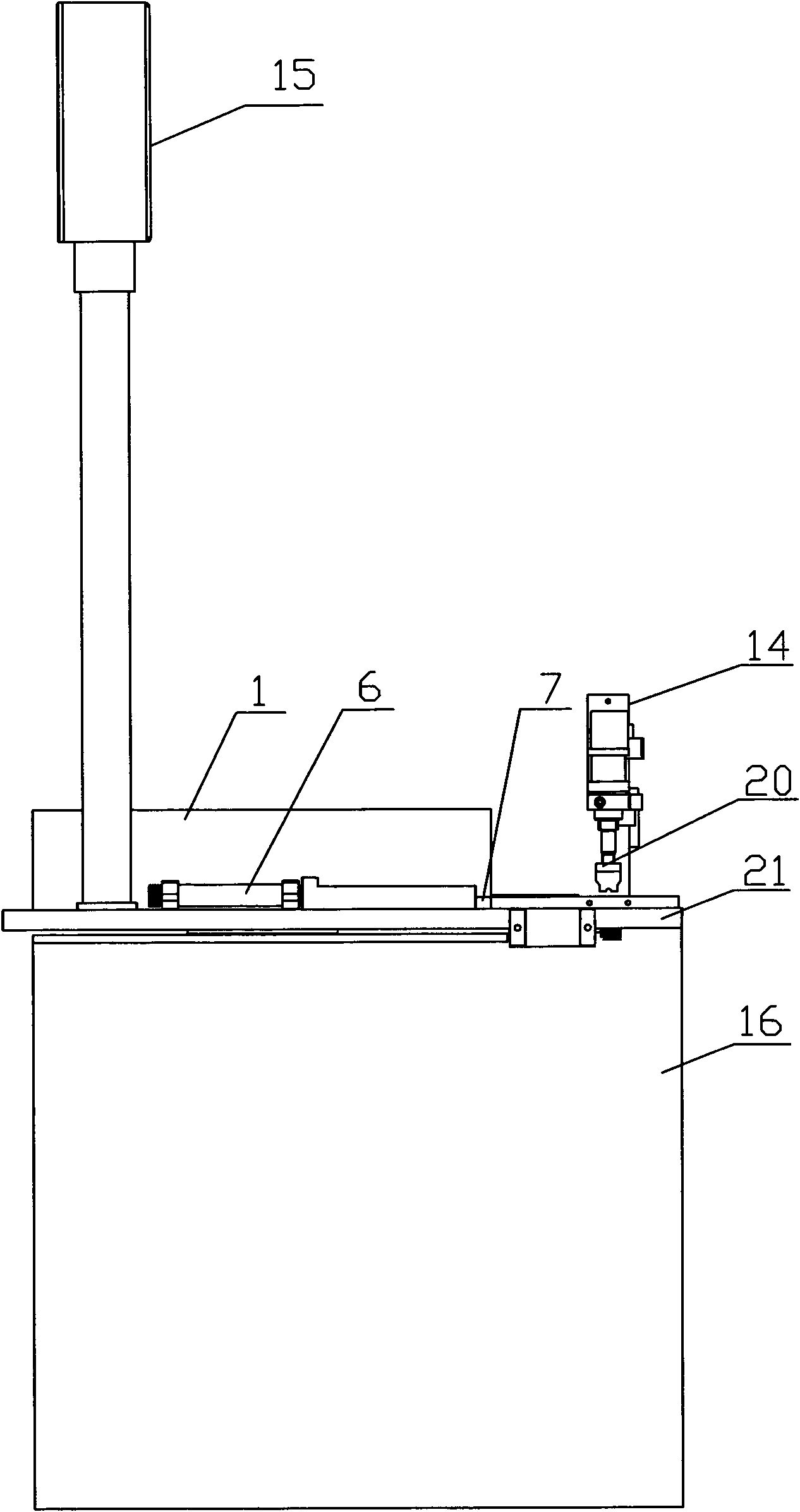
[0017] Refer to the attached figure 1 to attach image 3 The fully automatic bearing greaser of the present invention is described in detail below.

[0018] The structure of the fully automatic bearing greaser of the present invention includes a grease supply device, a workbench 21, a frame 16 arranged below the workbench 21, a greaser device and a disc 1 arranged above the workbench 21, the described The grease supply device is connected with the fat adding device, and the described fat adding device includes a quantitative oil filling valve 12, an oil delivery plate 13 and an oil injector 14, and the described quantitative oil injection valve 12 is connected with the oil injector 14 through the oil delivery plate 13, and the described The lower part of the oil injector 14 is provided with an oil head 20, the disc 1 is provided with a turntable 2, the disc 1 and the workbench 21 are directly welded together, and the disc 1 adopts a cut-out structure , a section is cut off a...


PUM


Abstract

The invention discloses a full-automatic bearing grease feeder and belongs to a grease feeder. The grease feeder comprises a grease supplying device, an operation platform, a frame, a grease feeding device and a round plate, wherein the grease supplying device is connected to the grease feeding device; the grease feeding device comprises a rationally greasing valve, a grease transmitting plate and a grease injector; the lower part of the grease injector is provided with a grease head; a rotation plate is arranged in the round plate; the round plate is welded with the operation platform; the round plate is provided with a rejected type structure; one section of the joint between the round plate and a material channel is cut off; a clearance is leaved between the upper port on the cut part of the round plate and the bottom of the rotation plate; the rotation plate is connected to a motor; the upper surface of the rotation plate is in a same level with the upper surface of the operation platform; the operation platform is provided with a material pushing device and a touch screen; and the operation platform outside the round plate is provided with a discharge regulating device. The invention has simple manufacturing process, saves vast manpower and material resources, is easily regulated when the size is exchanged, has strong generality, can automatically remove the materials stored in the round plate, has small volume, is convenient to clean, and has the advantages of high efficiency, high intensity, light weight, material saving property, and the like.

Description

technical field [0001] The invention relates to a greaser, in particular to a fully automatic bearing greaser. Background technique [0002] The existing bearing greaser disc adopts a landslide structure, relying on steel plates to form a material path, the structure is complex, and processing is difficult. It is difficult to adjust when changing the model, the vibration is large, and the noise is large. Manpower; the oil injection valve part adopts the purchased cylinder, which is assembled with the purchased valve body. The whole looks patchy, with complex shape, large volume, long oil passage, low efficiency, and it is not easy to wipe when there is dust or other dirt; frame The steel pipe welding structure is used, which wastes materials. The overall structure is complex, consumes a lot of energy, and installation, commissioning, and maintenance are difficult. Due to the shortcomings of various links, the overall volume is large, the appearance is uncoordinated, and the ...

Claims


Application Information

Patent Timeline
IPC IPC(8): F16N7/38F16N23/00
Inventor 曲建华宋艳
Owner SHANDONG XUNJIE PRECISION EQUIP
Learn More