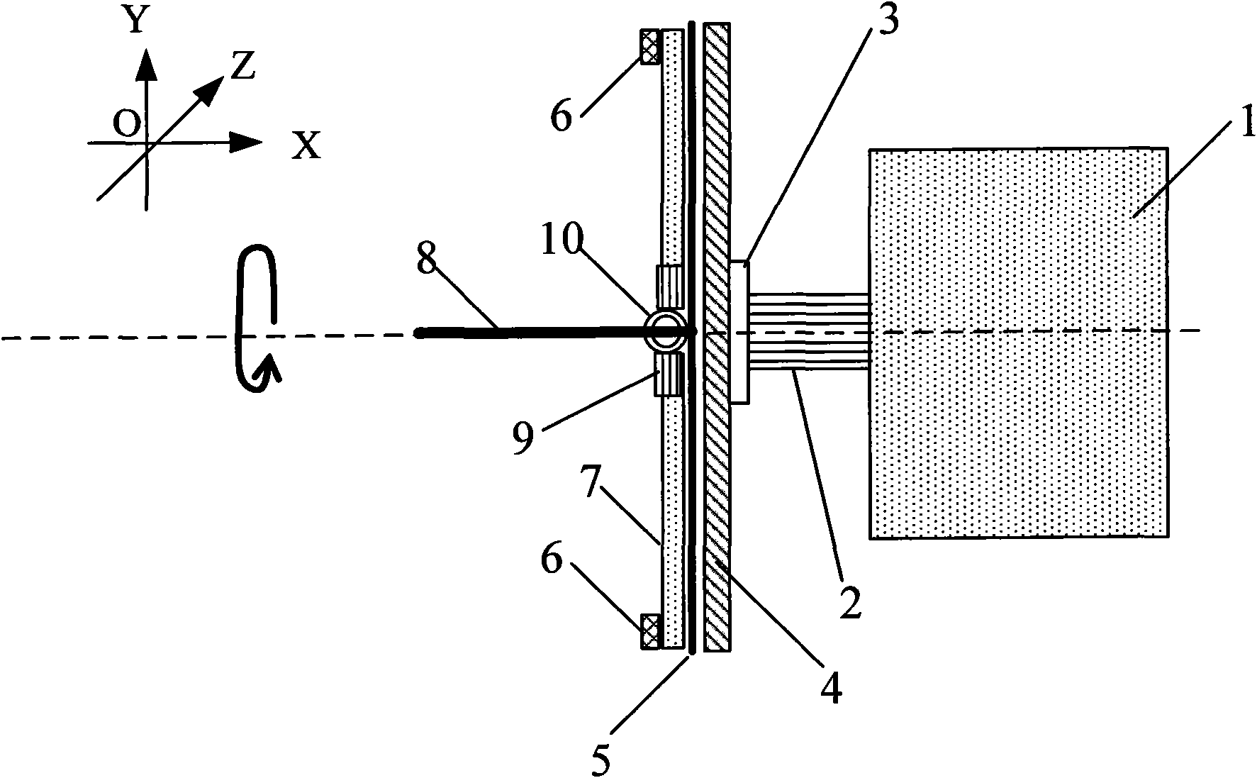
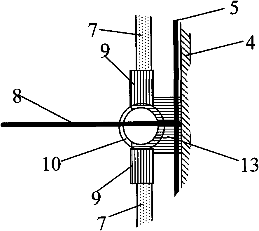
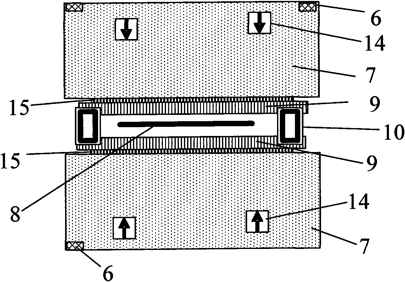
[0026] The preferred embodiments of the present invention are given below in conjunction with the accompanying drawings to describe the technical solution of the present invention in detail.
[0027] The invention provides a test device and a test method for the static performance index of a three-axis miniature accelerometer. like Figure 1-5 As shown, the device for testing the typical performance indicators of the three-axis micro accelerometer in the present invention includes: motor 1, transmission shaft 2, flange 3, test motherboard 4, Y direction positioning plate 5, spacer block 6, test board 7, X direction The positioning board 8 , the slot 9 , the rotating device 10 , the connecting device 13 , the positioning slot 14 of the device under test and the lead bar 15 on the test board 7 . The motor 1 provides power for the rotation of the test platform, and the test platform can rotate along the direction of rotation; the transmission shaft 2 is the power transmission device of the motor 1, which transmits power for the rotation of the test platform; the flange 3 connects the test motherboard 4 and The device 13 is fixed on the drive shaft 2; the test motherboard 4 is installed on the flange 3, and the test motherboard 4 is equipped with a test circuit for testing device signals, and is connected to the lead bar 15 on the test board 7 through the slot 9 Connect electrical signals to measure devices and output signals, the output signals can be voltage signals or capacitance signals; Y-direction positioning plate 5 and X-direction positioning plate 8 form a firm "T"-shaped orthogonal structure, and are fixed on the connecting device 13 Above; the spacer block 6 is fixed on one end of the test board 7, and after the rotating device 10 completes the 90° rotation, it is ensured that the test board 7 is kept parallel to the X-direction positioning board 8; It is placed symmetrically on the axis of rotation of the motor 1. The test board 7 is equipped with a positioning groove 14 of the device under test. Insert the end with the lead bar 15 into the slot 9, and the positioning groove 14 of the device under test can be formed with the test motherboard 4. Electrical signal connection; the slot 9 is installed on the rotating device 10, and is respectively placed on both sides of the positioning plate 8 in the X direction, and is connected with the test motherboard 4 by wires, and the slot 9 has a lead bar 15 inside; the rotating device 10 is installed On the connecting device 13, it is possible to turn over the Z axis at 90 degrees in the XOY plane and the Y axis; the connecting device 13 is fixed on the flange 3 for mechanically connecting the rotating device 10, the X direction positioning plate 8 and the Y direction The positioning plate 5 ensures that the rotating device 10 and the slot 9 above it and the test plate 7 with the spacer 6 can rotate together with the rotation of the motor 1; the device under test positioning groove 14 is installed on the test plate 7, and the The device under test can be installed on the positioning groove 14 of the device under test, the direction of the Y sensing axis of the device under test is upward, and the direction of the X sensing axis is perpendicular to the drive shaft 2. At least one device under test can be installed on each test board 7, and the direction of the sensing axis of the device under test is upward. Device is an accelerometer device, can be uniaxial accelerometer, biaxial accelerometer or triaxial miniature accelerometer; Signal.
[0028] The test method of the static performance index of the three-axis miniature accelerometer of the present invention is to apply an acceleration of one earth gravitational unit to the accelerometer device through the action of gravity, define one gravitational acceleration unit as 1g, and the direction is always vertically downward. The axis direction of the accelerometer device is changed by the rotation of the motor and the flipping of the test board, so that it is affected by the acceleration of the three axes under the action of gravity, so as to test the accelerometer device in the three sensing axes on the performance indicators. According to this test method, the present invention is also suitable for testing the performance of single-axis and dual-axis accelerometers. When the direction of the sensing axis of the measuring device is parallel to the direction of the Y axis, first place the direction of the sensing axis of the accelerometer device under the action of +1g, and fine-tune the rotation angle of the motor to maximize the measured output signal, then you can Determine the actual sensing axis direction of the accelerometer device, whose output signal is U 1; In the same way, after rotating 180 °, the maximum output data U of the accelerometer device under the effect of -1g is obtained 2.
[0029]When the motor rotates, the present invention drives the device to rotate in the YOZ plane, so that the gravity direction of the accelerometer device is changed in the Y and Z directions; after the test board is turned 90° along the Z axis in the XOY plane, the acceleration The X-axis of the accelerometer device is in the Y direction. When the motor rotates, the device is driven to rotate in the YOZ plane, and the X-sensing axis of the accelerometer device is affected by gravity, thereby completing the device in the three axes of X, Y, and Z. Therefore, one test can complete the performance tests on three axes.
[0030] Wherein, the test of the X axis of the present invention comprises the following steps:
[0031] A1. Before the test board is turned over, the test board surface is perpendicular to the axis of motor rotation. At this time, the X sensing axis of the accelerometer device is parallel to the axis of motor rotation, and the induction signal is 0.
[0032] A2, after the test board is turned 90° along the Z axis in the XOY plane, since the direction of the Z sensing axis of the accelerometer device is not changed by gravity, the performance of the accelerometer device in the direction of the Z sensing axis will be tested again. By comparing the two test results, it can be ensured that the test board is flipped at an angle of 90°. At this time, the test board surface is parallel to the axis of rotation of the motor.
[0033] A3, after the test board is turned 90° along the Z axis in the XOY plane, the direction of the X sensing axis of the accelerometer device is parallel to the direction of the Y axis.
[0034] A4, under the action of gravity, before the motor rotates, the X sensing axis signals of the accelerometer device are -1g (upper board) and +1g, when the rotation is 180°, the test X sensing axis signals are +1g and -1g.
[0035] Wherein the test of Y-axis and Z-axis of the present invention comprises the following steps:
[0036] B1, first test the signal of the Y sensing axis +1g, at this time, the direction of the Z sensing axis is perpendicular to the direction of gravity, and the sensing signal is 0. Drive the motor to rotate 90° clockwise, and test the signal of +1g on the Z sensing axis. At this time, the direction of the Y sensing axis is perpendicular to the direction of gravity, and the sensing signal is 0. Drive the motor to rotate clockwise to 180°, and test the signal of the Y sensing axis -1g. At this time, the direction of the Z sensing axis is perpendicular to the direction of gravity, and the sensing signal is 0. Drive the motor to rotate clockwise to 270°, and test the signal of the Z sensing axis -1g. At this time, the direction of the Y sensing axis is perpendicular to the direction of gravity, and the sensing signal is 0.
[0037] After the measurement of B2, Y, and Z axes, the drive motor rotates 270° counterclockwise and returns to the initial position.
[0038] In the above method, while determining the output signal of the device under the action of positive and negative gravitational acceleration, the actual sensitive direction of the device is also determined. The angle between the secondary sensitive direction and the sensitive direction calibrated by the device is the axis of the device poor angle. Of course, the measurement accuracy of the shaft center difference angle is related to the step accuracy of the rotation angle of the motor. Since the output signal on the axis is proportional to the cosine of the angle, even if the accelerometer is not in the quadrature orientation, the resulting error is not very large. For example, if there is a 5° direction deviation, the measurement result will have an error of about 0.4%. In order to improve the accuracy of the measurement, the actual measurement error is reduced by reverse rotation, multiple measurements, and averaging. Since the method of operating the measuring device is simple, the above method of error elimination is easy to implement.
[0039] Of course, static biasing is a ubiquitous phenomenon for the accelerometer device itself. Suppose the output data under the action of positive and negative gravitational acceleration are respectively U 1 ’, U 2 ’, the sensitivity is S, and the static bias is U off , then formula (1) is satisfied:
[0040] u 1 '=Sx1g+U off; 2 ’=Sx(-1g)+U of --------Formula 1)
[0041] Therefore:
[0042] The sensitivity S of the device is: S=(U 1 ’-U 2 ’)/2, unit: per g
[0043] The static bias of the device U off For: U off =(U 1 ’+U 2 ')/2
[0044] On this basis, if the device to be tested is a single-axis micro-accelerometer, then, according to the above-mentioned operation method, the lateral sensitivity of the device can also be measured, that is, when the accelerometer device is subjected to an acceleration perpendicular to the direction of the sensitive axis, The ratio of output to input acceleration in the direction of its sensitive axis. Rotate the uniaxial accelerometer to the direction perpendicular to the sensitive axis of the device, that is, at 90° and 270°, and then calculate the measured output data using the above sensitivity formula to obtain the lateral sensitivity of the device.
[0045] If the accelerometer to be tested is a three-axis accelerometer, the sensitivity and static bias in the X and Y directions can be directly measured by using the above method. And for the performance test on the Z-axis direction, only need to turn over the test board 7 to such as Figure 4 shown in the position, it can be achieved. Its specific operation steps are:
[0046] i) First measure the sensitivity of the accelerometer device in the Y and Z directions before it is turned over;
[0047] ii) After flipping the test board, measure the sensitivity in the Z direction again to ensure that the results of the device performance test before and after flipping are consistent;
[0048] iii) When the results of the above two-step tests are consistent, or within the allowable error range, then drive the motor to rotate, so that the axis of the accelerometer device to be tested is rotated to the direction orthogonal to the original direction, such as Figure 4 As shown, that is, at 90° and 270°, thereby completing the performance test of the accelerometer device in the X-axis direction.
[0049] In addition, according to the driving capacity of the motor, the carrying capacity of the test device, and the requirements of test accuracy, the area of the test board can be customized according to the requirements. By testing multiple devices at a time, the test efficiency can be greatly improved. Reduce the cost of testing.
[0050] Finally, from the test process, it can be found that changing the force direction of the device, especially when testing the performance when the sensing axis is the X axis, does not need to change the force direction of the device through manual disassembly as in the traditional measurement method. The operation process is made more convenient, and not only the accuracy of the test can be guaranteed, but also the efficiency of the test can be improved. Testing of performance indicators such as sensitivity, shaft center difference angle, and static bias. At the same time, by appropriately changing the conditions such as temperature and humidity of the test environment, the test of the related performance of the accelerometer based on this test device can be completed. For example, by changing the test environment, it is also possible to test device performance under different environmental conditions, such as: the impact of different temperatures and humidity on device performance, etc.
[0051] Although the specific implementations of the present invention have been described above, those skilled in the art should understand that these are only examples, and various changes or changes can be made to these implementations without departing from the principle and essence of the present invention. Revise. Accordingly, the protection scope of the present invention is defined by the appended claims.