Main transformer differential protection CT polarity check method of pumped storage power station

A pumped-storage power station and main transformer technology, applied in the measurement of electrical variables, emergency protection circuit devices, instruments, etc., can solve the problem of the inability to verify the CT polarity of the main transformer differential protection, and reduce the production cost and save investment. , the effect of simple operation and use conditions

Inactive Publication Date: 2011-01-26
湖北白莲河抽水蓄能有限公司
View PDF1 Cites 30 Cited by
  • Summary
  • Abstract
  • Description
  • Claims
  • Application Information

AI Technical Summary

Problems solved by technology

[0003] The purpose of the present invention is to solve the problem that the polarity of the protective CTs such as the main transformer differential, bus differential and high-voltage cable differential cannot be verified when the main transformer is reversed before the unit is started, and a CT polarity verification method for the differential protection of the main transformer of the pumped storage power station with simple operation and use conditions, saving investment, and not occupying the straight-line construction period of the water commissioning of the unit

Method used


Image

  • Main transformer differential protection CT polarity check method of pumped storage power station
  • Main transformer differential protection CT polarity check method of pumped storage power station
  • Main transformer differential protection CT polarity check method of pumped storage power station

Examples


Embodiment 1

[0023] Embodiment 1: Taking a main transformer with a capacity of 360MVA and 500KV as an example to introduce the polarity verification method of the differential protection of the main transformer.

[0024] (1) The polarity verification method of the differential protection of the main transformer of the present invention is the short-circuit step-up method on the low-voltage side of the main transformer or the method of externally applied power supply.

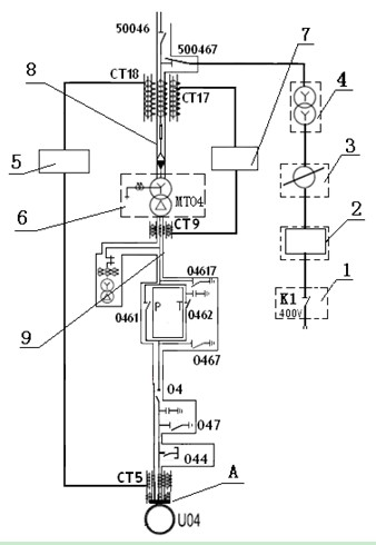
[0025] (2) Test conditions of the method of the present invention: the capacity of the main transformer 6 of the present invention is 360MVA, the rated voltage is 525KV / 15.75KV (intermediate gear), the rated current is 396A / 13197A, the connection group label is YN d11, the short circuit impedance It is 14% (this value can be obtained by querying the parameters of the main transformer).

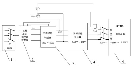
[0026] The equipment prepared for the verification of the present invention includes: a power inlet switch K1, a three-phase test voltage...

Embodiment 2

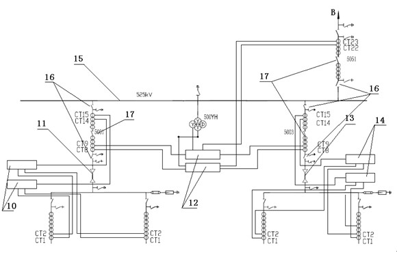
[0060] Embodiment 2: Using the method for verifying the polarity of the differential protection of the main transformer of the present invention, the CT polarity of the differential protection of the 500KV GIS bus 15, the first high-voltage cable 11, and the second high-voltage cable 13 of the power station is checked. Its differential protection CT configuration diagram is as follows: image 3 . Before the primary equipment is officially powered on, it is necessary to complete the busbar differential protection A\B set 12, the first high-voltage cable 11, the second high-voltage cable 13, the first differential protection A\B set 10, the second high-voltage CT polarity verification of A\B sets 14 of cable differential protection. The capacity of the test equipment only needs to be considered plus the charging current of the first and second high-voltage cables, and the pressure point is selected at image 3 In point B, the applied voltage is not affected by figure 1 Medium...


PUM


Abstract

The invention relates to a main transformer differential protection CT polarity check method of a pumped storage power station. In the invention, an applied power method is adopted to solve the problem that the main transformer differential, bus differential and high-voltage cable differential protection CT polarity cannot be checked during the inversed electrification of a main transformer before the machine set of the power station is started, thereby the safety and reliability of the system and the inversed electrification of the main transformer are ensured. The method has the advantages that the operation and the using condition are simple, the used test instrument equipment can be used repeatedly, the water debugging straight-line period of the machine set is not occupied, the temporary high-voltage cable investment is saved, and the commissioning cost is reduced; therefore, the method has favorable popularization and application prospect.

Description

technical field [0001] The invention relates to a CT polarity verification method for a main transformer differential protection of a pumped storage power station. Background technique [0002] Due to the particularity of the pumped storage power station, most of the pumped storage power stations have no natural water in the upper reservoir before the first unit is started. In the part of the test, the upper storage water is difficult to verify the CT polarity of the main transformer differential protection through the unit with the main transformer zero upflow; the second unit must have an external power source to drive the unit when the water pump is started. Therefore, before the start of the first unit of the energy storage power station, it is generally necessary to complete the power receiving operation of the main transformer. One of the necessary conditions for the reverse power supply of the main transformer is to ensure that the polarity of the differential protec...

Claims


Application Information

Patent Timeline
Patent Type & Authority Applications(China)
IPC IPC(8): H02H7/045G01R31/06
Inventor 杨洪涛景城穆显勇
Owner 湖北白莲河抽水蓄能有限公司
Why Eureka
Try Eureka