
Optical lens assembly

A technology for optical lenses and components, applied in optical components, optics, instruments, etc., can solve the problems of not being light, thin, short, increase the volume of the lens, increase the production cost, etc., and achieve the effect of good optical performance, shortening the total length, and reducing the cost.

Active Publication Date: 2012-06-20
深圳市合力泰光电有限公司
View PDF0 Cites 0 Cited by
  • Summary
  • Abstract
  • Description
  • Claims
  • Application Information

AI Technical Summary

Problems solved by technology

Especially in lens modules with more than one million pixels and some micro-scanning devices, in order to ensure high imaging quality, brightness and sufficient field of view, digital imaging systems require a large space to inflect light, often by increasing the number of lenses and lens material to correct aberrations and improve imaging quality; the length of this product is far from meeting the requirements of thinness and shortness. On the one hand, it increases the size of the lens and also leads to an increase in production costs

Method used


Image

  • Optical lens assembly
  • Optical lens assembly
  • Optical lens assembly

Examples


Embodiment 1

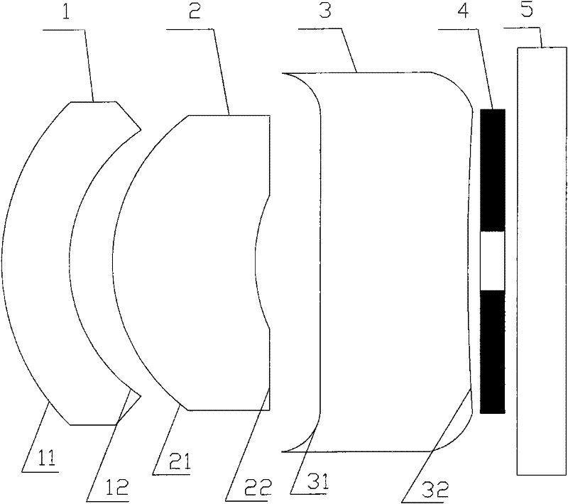
[0021] figure 1 It is a structural schematic diagram of the optical assembly of Embodiment 1 of the optical lens assembly of the present invention.

[0022] Such as figure 1 As shown, an optical lens assembly includes a lens group, and the lens group includes a first lens 1, a second lens 2 and a third lens 3 that are coaxial and arranged in sequence from the object side to the image side; the first lens 1 has a lens facing the object The second lens 2 has a third surface 21 facing the object side and a fourth surface 22 facing the image side, and the third lens 3 has a fifth surface facing the object side 31 and the sixth surface 32 facing the image side; the first surface 11, the second surface 12, the third surface 21, and the fourth surface 22 are all aspheric surfaces; the first surface 11 is a convex surface, and the second surface 12 is a concave surface The center of the third surface 21 is a convex surface, and the edge is a concave surface; the center of the fourth...

Embodiment 2

[0037] In the second embodiment provided by the present invention, on the basis of the first embodiment, the relevant parameters of the lens assembly are further proposed as follows:

[0038] Lens parameters:

[0039] Types of

Radius of curvature (R)

Quadratic coefficient (k)

Thickness (dmm)

first surface

1.325643

0

0.25

second surface

1.060042

0

0.21

third surface

7.520604

-0.7571741

0.47

fourth surface

0.523487

-3.743714

0.03

fifth surface

2.75364

-0.325276

0.46

sixth surface

1.253978

0

0.08

Filter Front Surface

0.3

Filter rear surface

0.03

Protective glass front surface

0.4

Protective glass rear surface

0.08

Image surface

0

[0040] Aspherical Coefficient:

[0041] Types of

a 1

a 2

a 3

a 4

a ...

Embodiment 3

[0048] In the third embodiment provided by the present invention, on the basis of the first embodiment, the relevant parameters of the lens assembly are further proposed as follows:

[0049] Lens parameters:

[0050] Types of

Radius of curvature (R)

Quadratic coefficient (k)

Thickness (dmm)

first surface

0.286928

-0.9151723

0.44

second surface

6.060042

-109.6843

0.22

third surface

1.877226

0

0.45

fourth surface

5.569566

0

0.03

fifth surface

2.6513287

0

0.43

sixth surface

0.3987561

0

0.06

Filter Front Surface

0.3

Filter rear surface

0.03

Protective glass front surface

0.4

Protective glass rear surface

0.11

Image surface

0

[0051] Aspherical Coefficient:

[0052] Types of

a 1

a 2

a 3

a 4

...


PUM

PropertyMeasurementUnit
refractive indexaaaaaaaaaa

Abstract

The invention relates to the optical field, and provides an optical lens assembly. The optical lens assembly comprises a first lens, a second lens and a third lens which are coaxially and sequentially arrayed from an object space to an image space, wherein the first lens is provided with a convex first surface and a concave second surface, the second lens is provided with a third surface and a fourth surface, and the third lens is provided with a fifth surface and a six surface; all the surfaces are aspheric surfaces; the optical lens assembly satisfies the following conditions that: L / f is more than 1.1 and less than 1.35, f1 is more than 0, the absolute value of f / f1 is more than 0.5 and less than 1.2, f2 is more than 0, the absolute value of f2 / f is more than 0.9 and less than 2.2, f3 is less than 0, and the absolute value of f3 / f is more than 0.55 and less than 2.2, wherein f and L are effective focal length value and total length of the optical system respectively; and f1, f2 andf3 are effective focal lengths of the first, second and third lenses. The total length of the lens is shortened by adopting the three lenses and the combination of positive, positive and negative diopters; and each aberration is welled corrected so that good optical performance is obtained.

Description

technical field [0001] The invention relates to optical devices, in particular to an optical lens assembly. Background technique [0002] In digital imaging equipment, the optical imaging lens is a particularly important component, and the image quality of the lens directly determines the imaging performance of the digital imaging equipment. At the same time, digital products are constantly being updated, and are increasingly becoming thinner and shorter, and there are higher and higher requirements for optical lenses equipped in digital imaging equipment. Especially in lens modules with more than one million pixels and some micro-scanning devices, in order to ensure high imaging quality, brightness and sufficient field of view, digital imaging systems need a large space to inflect light, often by increasing the number of lenses The method of correcting the aberration and improving the image quality by using the lens material method; the length of this product is far from m...

Claims


Application Information

Patent Timeline
Patent Type & Authority Patents(China)
IPC IPC(8): G02B13/00G02B13/18G02B1/04G02B1/00
Inventor 刘海生
Owner 深圳市合力泰光电有限公司
Learn More