Standby zero power consumption switch control system

A switch control system and zero power consumption technology, applied in electronic switches, electrical program control, information technology support systems, etc., can solve the problems of disconnection and long-term connection of the charging circuit to the power grid, and achieve the effect of zero power consumption

Active Publication Date: 2011-02-02
CHANGZHOU KAIDI ELECTRICAL INC
View PDF9 Cites 26 Cited by
  • Summary
  • Abstract
  • Description
  • Claims
  • Application Information

AI Technical Summary

Problems solved by technology

[0004] The technical problem to be solved by the present invention is to propose a method that overcomes the defect that the charging circuit is connected to the power grid for a long time without using a battery as a backup power supply, and at the same time solves the problem of switching between running and stopping multiple times in a short period of time. , the switching device of the main power supply will also be closed with each operation-disconnection problem

Method used


Image

  • Standby zero power consumption switch control system
  • Standby zero power consumption switch control system
  • Standby zero power consumption switch control system

Examples


Embodiment Construction

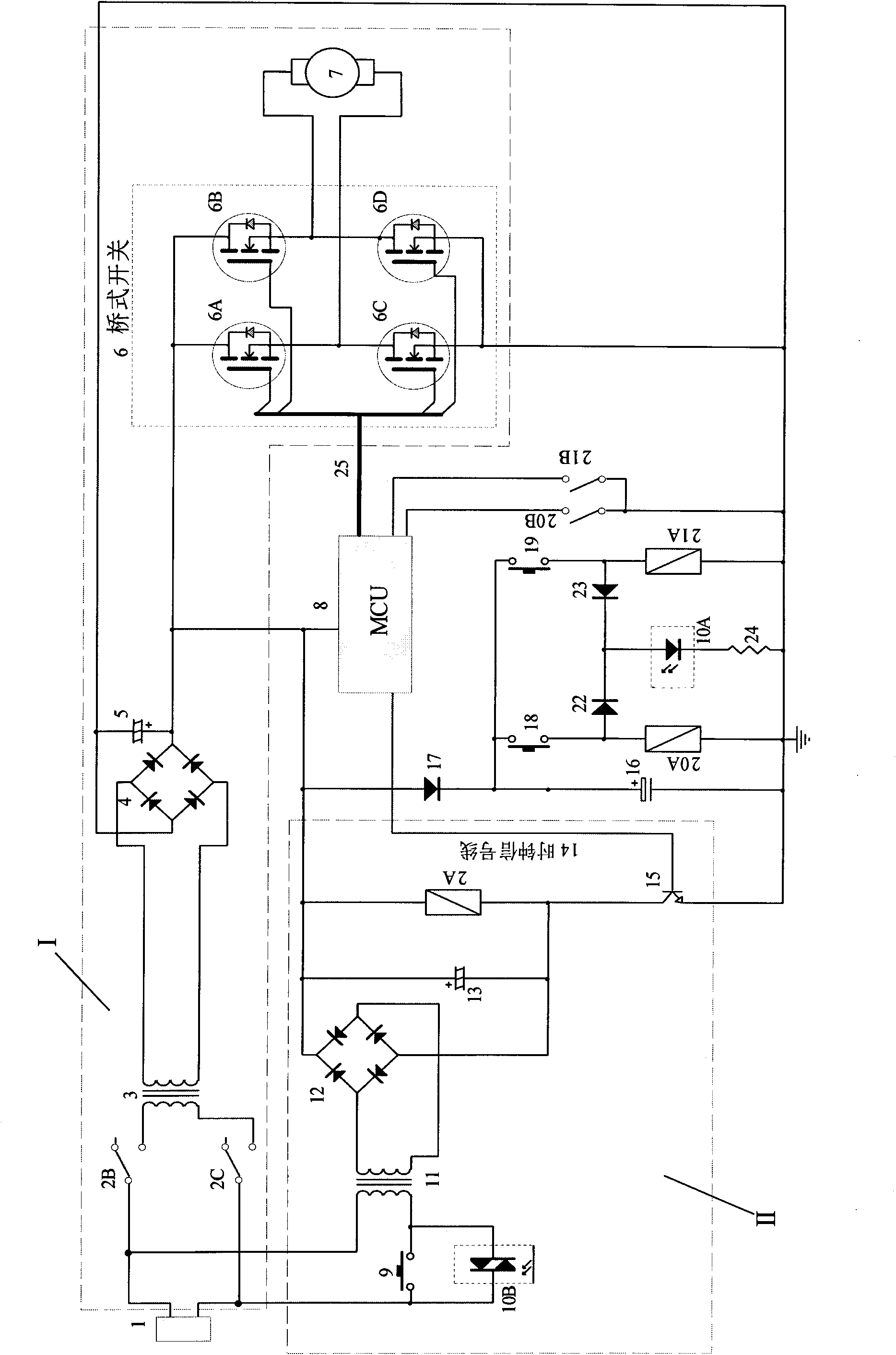
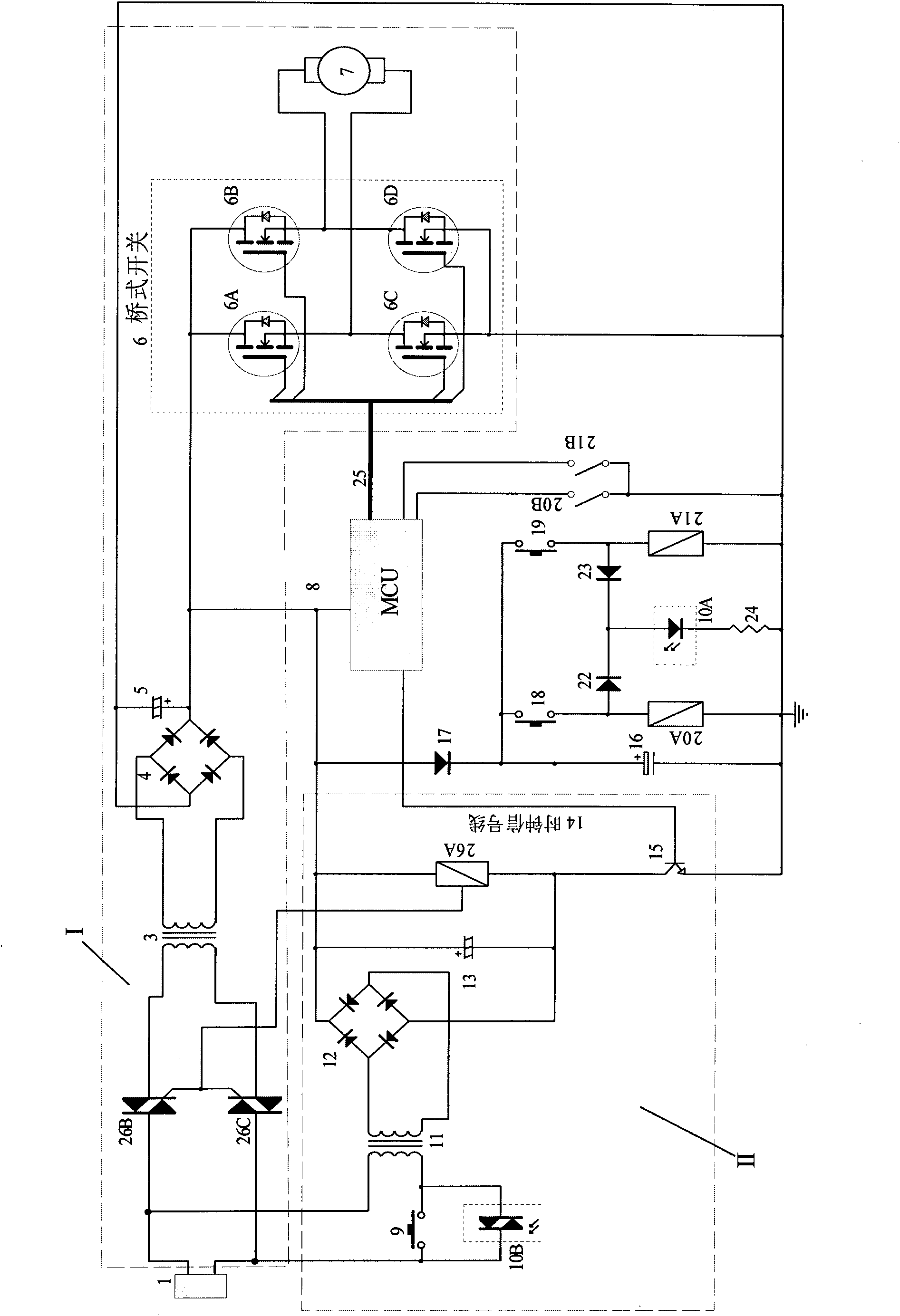
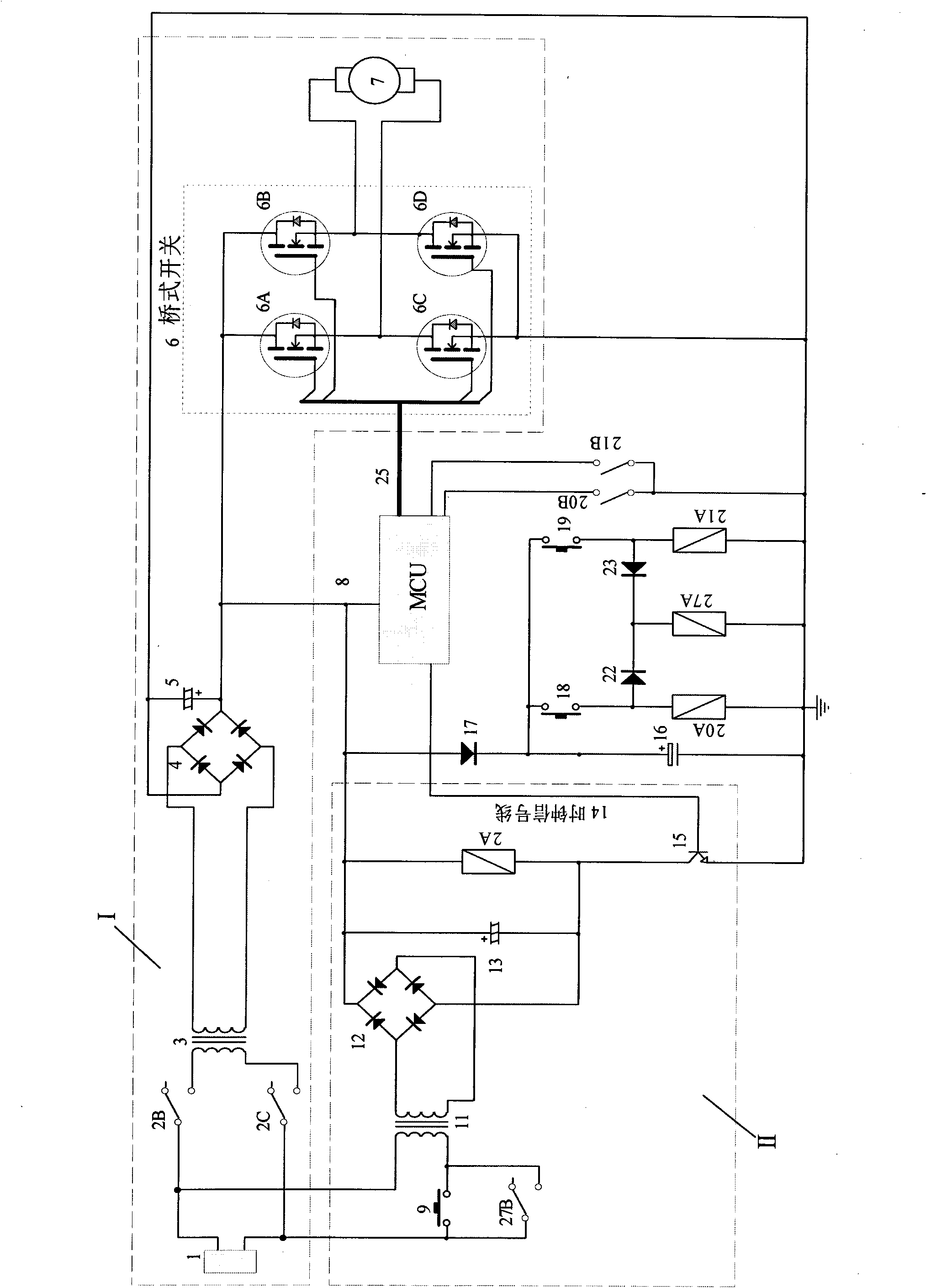
[0017] The present invention will now be described in further detail in conjunction with the accompanying drawings and preferred embodiments. These drawings are all simplified schematic diagrams, which only illustrate the basic structure of the present invention in a schematic manner, so they only show the configurations related to the present invention.

[0018] Such as figure 1 As shown, the dotted box I is the main circuit, 1 is the main power supply, 2B and 2C are the main circuit switches, here we use relays, 3 is the main circuit transformer, 4 is the main circuit rectifier bridge, 5 is the main circuit filter capacitor, 6 is The H-bridge switch circuit, the drive module 8 composed of a single-chip microcomputer and peripheral components transmits the control signal of the H-bridge switch 6 through the bus 25, so that different bridge arms are turned on, and the motor 7 is respectively operated in the forward and reverse directions. When the switch 20B is closed, the dr...


PUM


Abstract

The invention relates to a standby zero power consumption switch control system, which is used for electrically adjusting civil and industrial electrical appliances. In an automatic switch device for the on / off of a main power supply, a main circuit switch is arranged at the front end of the main circuit; the switch is controlled by a driver in a control circuit, automatically delays for disconnection when being not used by the system and is automatically closed when being used by the system. A control circuit switch is arranged at the front end of the control circuit, is automatically disconnected when being not used by the system and is automatically closed when being used by the system, thereby realizing zero power consumption, that is to say, the main circuit and the control circuit do not consume electric energy in standby; and meanwhile, only once on / off action is needed to be performed on the switch for the on / off of the main power supply when the system is operated in short time for multiple times.

Description

technical field [0001] The invention relates to a power switch device, in particular to an automatic switch device suitable for controlling the on-off of the main power supply of current-consuming equipment, which is used to turn off and start the main power supply of the system and realize zero power consumption during standby. Background technique [0002] At present, electrically adjustable office furniture, hospital beds, sofas, household appliances, and industrial electrical equipment are more and more widely used. In some cases, we will want to keep this kind of electric regulating equipment and main power disconnected. Electromagnetic fields are generated in some special occasions, such as wards. The most complete shutdown can be achieved by manually turning off the main power switch installed on the equipment or directly pulling its power plug out of the grid. However, this requires that the power plug must be manually turned on or plugged in when the equipment is r...

Claims


Application Information

Patent Timeline
Patent Type & Authority Applications(China)
IPC IPC(8): H03K17/78G05B19/04
CPCH02J2009/007H02J9/005H02J9/007Y02B70/30Y04S20/20
Inventor 周斌姚步堂唐克勇
Owner CHANGZHOU KAIDI ELECTRICAL INC
Why Eureka
Try Eureka